

4 layers99 × 53.3 mm
PSLab
fossasia/pslab-hardware
PSLab Hardware Design and Schematics https://pslab.io
199 parts1.7kApache-2.0
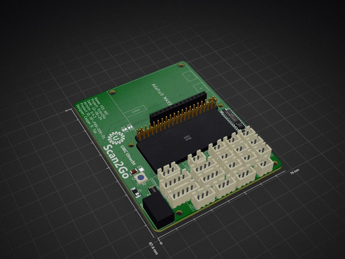
This repository houses the Ferrous Metal Detection Gate (FDS in Dutch), a system designed to enhance safety by preventing ferrous metal passage into the MRI room. The FDS incorporates a Raspberry Pi Pico and a Raspberry Pi 5 (RPI5), facilitating communication between the devices and various sensors.
HAT is an open-source printed circuit board by Casperdroid5, from the Casperdroid5/FDS-Scan2Go repository on GitHub. It is a 2-layer board of 76 × 97.6 mm with 45 parts on 97 nets, routed with 335 tracks and 213 vias.
It is built around the WS2812B. Its parts include 22 connectors, 3 ICs, 2 resistors, 2 diodes and 1 capacitor. It belongs with the RP2040 boards of this library.
The Ferrous Metal Detection Gate (FDS) is a sophisticated system designed to enhance safety for MRI room access by detecting ferrous metals. This system utilizes a Raspberry Pi Pico and Raspberry Pi 5 to facilitate communication with various sensors, providing both auditory and visual feedback to the user.
requirements_rpi5.txt for Raspberry Pi 5)requirements_pico.txt)Install Dependencies
Since the Pico runs on MicroPython for this project, you'll need to upload the required libraries manually or use a tool like mpremote.
mpremote mip install micropython-neopixel micropython-machine micropython-time micropython-i2c micropython-uartUpload Scripts to Pico
Upload the relevant .py files to the Pico:
mpremote fs cp hardware_s2g.py :hardware_s2g.py
mpremote fs cp system_utils.py :system_utils.py
mpremote fs cp main.py :main.pyPrepare MicroSD Card Install Raspbian 64-bit (with desktop) on a 32GB MicroSD card (using Raspberry Pi Imager, for example). Once installed, boot the Raspberry Pi 5, connect it to the internet, and open a terminal with root permissions.
Install Python Dependencies
pip install -r requirements_rpi5.txtInstall System Dependencies
sudo apt-get update
sudo apt-get install feh vlc
Run the Application Navigate to the project directory and start the main script:
python main.pymain.py script on the Raspberry Pi 5.We welcome contributions to the FDS-Scan2Go project. If you would like to contribute, please fork the repository and submit a pull request.
If you would like to emplement this code into your own project, ensure to give credit to the original author and mention any significant changes or improvements.
This project is licensed under the MIT License. See the DISCLAIMER file for more details.
| Qty | Value | Footprint | References |
|---|---|---|---|
| 11 | Conn_01x02_Socket | Connector_JST:JST_EH_B2B-EH-A_1x02_P2.50mm_Vertical | J2, J8, J9, J10, J12, J13, J14, J18, J19, J22, J24 |
| 6 | LOGO | LOGO | G***, G***, G***, G***, G***, G*** |
| 4 | Conn_01x03_Socket | Connector_JST:JST_EH_B3B-EH-A_1x03_P2.50mm_Vertical | J4, J5, J6, J16 |
| 4 | MountingHole | MountingHole:MountingHole_3.2mm_M3 | H1, H2, H3, H4 |
| 3 | Jumper_2_Open | Jumper:SolderJumper-2_P1.3mm_Open_TrianglePad1.0x1.5mm | JP1, JP2, JP3 |
| 2 | Conn_01x04_Socket | Connector_JST:JST_EH_B4B-EH-A_1x04_P2.50mm_Vertical | J7, J23 |
| 2 | Conn_01x05_Socket | Connector_JST:JST_EH_B5B-EH-A_1x05_P2.50mm_Vertical | J20, J21 |
| 1 | 0.1uF | Capacitor_SMD:C_1206_3216Metric_Pad1.33x1.80mm_HandSolder | C1 |
| 1 | 10K | Resistor_SMD:R_1206_3216Metric_Pad1.30x1.75mm_HandSolder | R2 |
| 1 | 3.9K | Resistor_SMD:R_1206_3216Metric_Pad1.30x1.75mm_HandSolder | R1 |
| 1 | 5 A | Fuse:Fuse_2010_5025Metric_Pad1.52x2.65mm_HandSolder | F1 |
| 1 | 5.0V | SamacSys_Parts:DIOM5436X261N | D1 |
| 1 | Conn_01x14_Socket | Connector_PinSocket_2.54mm:PinSocket_1x14_P2.54mm_Vertical | J3 |
| 1 | Jack-DC 5V | Connector_BarrelJack:BarrelJack_Wuerth_6941xx301002 | J15 |
| 1 | LM741 | Package_SO:SOIC-8_3.9x4.9mm_P1.27mm | U2 |
| 1 | MC14043BDR2G | SamacSys_Parts:SOIC127P600X175-16N | IC1 |
| 1 | Pico | MCU_RaspberryPi_and_Boards:RPi_Pico_SMD_TH | U1 |
| 1 | RPi_GPIO | _custom:Pin_Header_Straight_2x20 | J1 |
| 1 | TestPoint | TestPoint:TestPoint_Pad_2.0x2.0mm | TP1 |
| 1 | WS2812B | LED_SMD:LED_WS2812B_PLCC4_5.0x5.0mm_P3.2mm | D2 |
fossasia/pslab-hardware
PSLab Hardware Design and Schematics https://pslab.io

FrameworkComputer/ExpansionCards
Reference designs and documentation to create Expansion Cards for the Framework Laptop


PrintersForAnts/Micron
If you want to purchase full kits there are 3 available (Kits are slowly updating to R1 hardware just make sure to double check the included hardware in your kit and if you have any questions reach out in the discord)


It measures 76 × 97.6 mm and has 2 copper layers, 1.6 mm thick.
45 parts, built around the WS2812B. The full list of its parts is on this page, with links to each part's symbol and footprint where PCBKit's library has them.
From the Casperdroid5/FDS-Scan2Go repository on GitHub, at the commit this page was made from: the board is Hardware/RPI5-Scan2Go-HAT/HAT/HAT.kicad_pcb and its schematic Hardware/RPI5-Scan2Go-HAT/HAT/HAT.kicad_sch. PCBKit opens the board in the browser, with nothing to install.
Its repository states no licence, so its author keeps all rights: ask Casperdroid5 before reusing the design.