2 layers33 × 33 mm
DFR0264
fcl2002/Open-Ruche-Monitoring
An intelligent beehive monitoring solution combining embedded AI, LoRaWAN communication, and solar power to help beekeepers protect their colonies and optimize hive management.
15 parts1MIT

 CCHS-Melbourne/ESPlant37
Environmental Sensor Plant - solar WiFi gardening/meteorological sensor using ESP8266
ESPlant is an open-source printed circuit board by CCHS-Melbourne, from the CCHS-Melbourne/ESPlant repository on GitHub. It is a 2-layer board of 97 × 77.5 mm with 77 parts on 45 nets, routed with 993 tracks and 149 vias.
It is built around the STM32F042F4P6, ESP-12E and BME280, with the MCP6002-I/P, ADXL345-EP and CN3063 among its other parts. Its parts include 22 resistors, 13 connectors, 12 capacitors, 6 ICs and 5 diodes. It belongs with the radio and wireless and sensors and measurement boards and the ESP8266 and STM32 boards of this library.


Welcome to the linux.conf.au Open Hardware Project. You can see information about this and other MiniConfs at http://www.openhardwareconf.org/wiki/Main_Page
The ESPlant kit is designed to provide an open source platform to transmit environmental data to a central source using the power of wifi.
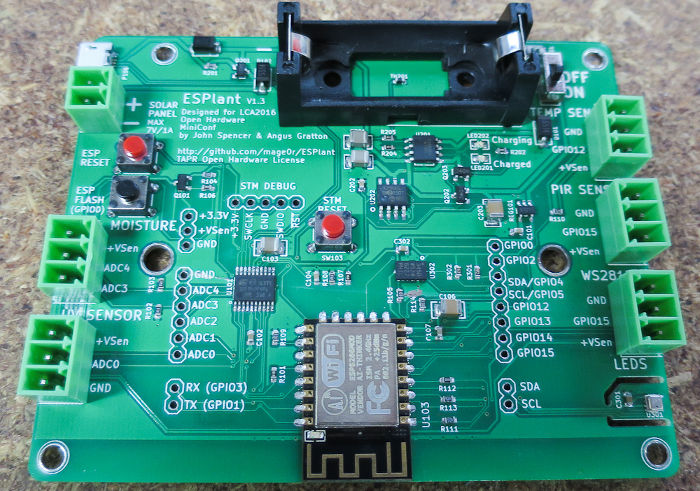
Assembled PCB:
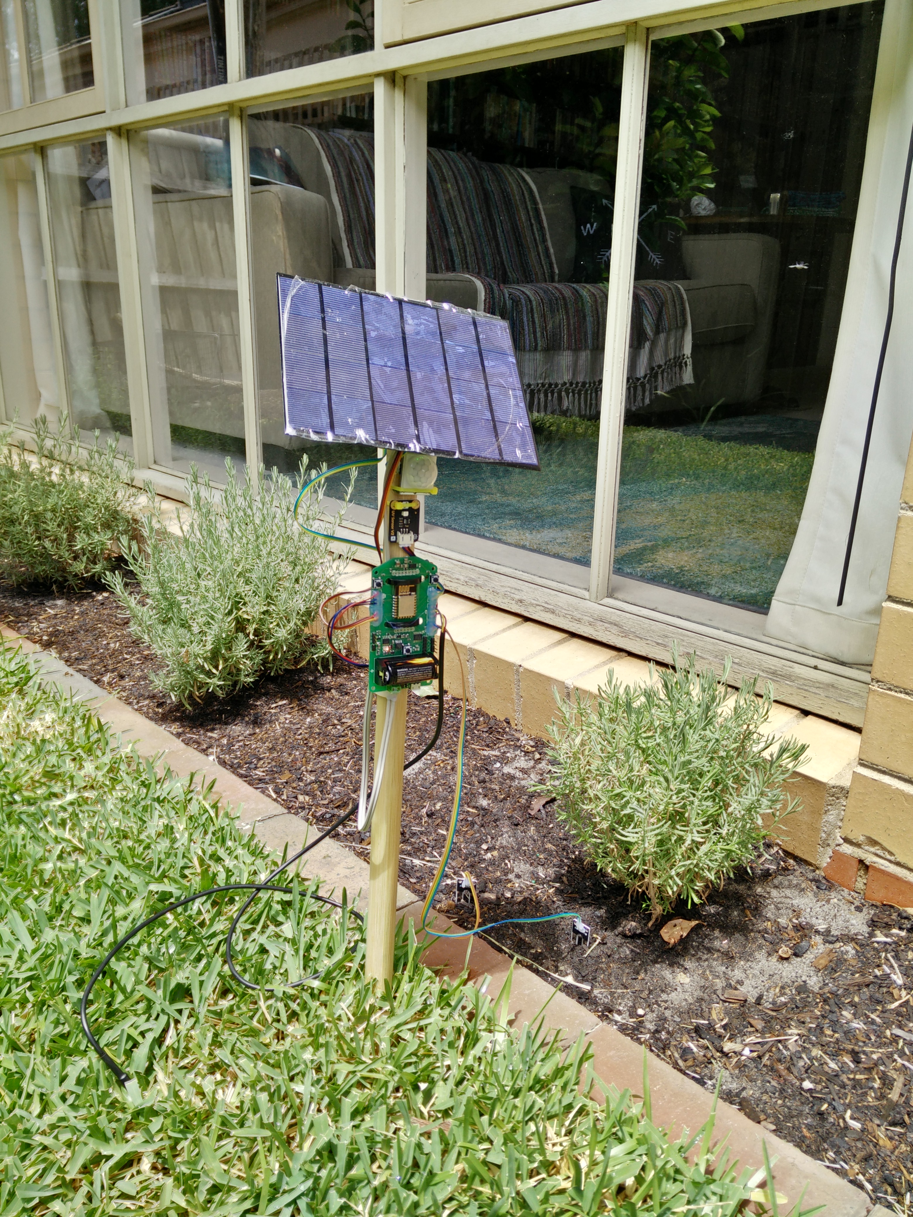
Prototype board in action (before significant changes):
Check out a video of pick-n-placing components of the boards you'll be getting at LCA 2016. https://www.youtube.com/watch?v=282qku2C4xo
The 3.3V "VSens" power rail is switchable on/off by the microcontroller. It defaults to unpowered (off). The GPIO to use is 14, and it is active low (ie driving the output low turns VSens on, driving it high turns it off).
To add ESP8266 support to the Arduino IDE (1.6.6 or newer) we use the external ESP8266 Arduino project. We need the staging version not the stable version of the ESP8266 support package.
Follow these steps to install:
http://arduino.esp8266.com/staging/package_esp8266com_index.json into Additional Board Manager URLs field. You can add multiple URLs, separating them with commas.You need to clone the ESPlant repo from github, using the --recursive option to pick up submodules. If you download a zip file then the submodule parts will be missing, so we recommend using git to get it.
The command is:
git clone --recursive https://github.com/CCHS-Melbourne/ESPlantArduino uses libraries to work with additional hardware or software functionality in an easy way. Normally you can download and install libraries directly inside the Arduino IDE by choosing Sketch menu -> Include Library -> Manage Libraries.
One library that you should install this way is the OneWire library. Search for "OneWire" and then click the Install button to install it.
For the ESPlant the other required libraries are set up as "git submodules" inside the "Libraries" directory. If you did a "recursive" clone then you will have these, otherwise you can add them to a "normal" clone by running this command:
git submodule update --initInside the Libraries directory there is a script install_libraries.sh that you can run on Linux or OS X to symlink all of the libraries into your Arduino libraries directory so you can use them.
cd Libraries
./install_libraries.sh
On Windows you'll need to copy all the subdirectories of the libraries directory (copy them into the My Documents/Arduino/libraries directory).
The one Library here that is part of this repo (not a submodule) is the "ESP_Kwai" library that acts as a bridge to the peripheral hardware.
Don't forget OneWire as well (see above).
After restarting Arduino IDE to pick up the new libraries, you're ready to upload your first program (Arduino calls them "sketches"):
Firmware/ESPlant_serial_sensor from this repository. This is a simple sketch that outputs all the analog values read by the board.The repo includes the following sketches:
ESPlant_prodtest is the hardware production test. It tests all the sensors to confirm the hardware is good. There are instructions in a large comment at the top of the sketch. You can run this if you think you're having hardware problems, or to look at example code for any individual point.
ESPlant_MQTT_sensor uses MQTT to push data to a server. It includes easy provisioning mechanisms for connecting to the WiFi. It has other instructions in its README file for WiFi configuration.
Check out (and contribute to) the wiki. There is a pinout summary, sensor summary, power information, etc.
There is an onboard STM32 microcontroller that acts as USB/Serial converter and an i2c connected ADC (Analog/Digital Converter) device.
For the i2c functionality, the ESP_Kwai library (under Libraries/ESP_Kwai) acts as a bridge (get it) to the i2c ADC peripherals on the ESPlant. It can automatically read all the values connected to the ADC and return them.
If you want more information on how the STM32 works internally, check out the README in the STM_Firmware directory.
This project was designed by the 2016 linux.conf.au Open Hardware Team!
Made at hackmelbourne.org!
To the HackMelbourne (CCHS, http://hackmelbourne.org) community of Melbourne, Australia.
To all other open-source developers whose countless hours supported every other aspect of this design.
The specific terms of distribution of this project are governed by the license referenced below. Please contact the copyright owner if you wish to modify the board for distribution. Please utilize this design for personal or research projects. Please acknowledge all contributors.
Licensed under the TAPR Open Hardware License (www.tapr.org/OHL). The "license" sub-folder also contains a copy of this license in plain text format.
Copyright John Spencer, Angus Gratton, Andy Gelme, Jon Oxer 2015
| Qty | Value | Footprint | References |
|---|---|---|---|
| 6 | 10K | FT:0603 | R104, R105, R109, R111, R113, R114 |
| 5 | 1K | FT:0603 | R101, R106, R112, R201, R202 |
| 4 | FDN340P | FT:SOT23_FET | Q101, Q201, Q202, Q203 |
| 4 | TEST_1P | Connect:1pin | MH101, MH102, MH103, MH104 |
| 3 | 100K 1% | FT:0603 | R102, R103, R108 |
| 3 | 100nF | FT:0603_CAP | C101, C102, C107 |
| 3 | 10uF 16V | FT:1210_CAP | C103, C201, C204 |
| 3 | SS14 | FT:DIODE_SMA | D101, D102, D201 |
| 2 | 100K | FT:0603 | R203, R206 |
| 2 | 100uF 16V X5R | FT:1210_CAP | C106, C203 |
| 2 | 1uF | FT:0603_CAP | C301, C302 |
| 2 | 4.7K | FT:0603 | R301, R302 |
| 2 | 7.15K 1% | FT:0603 | R204, R205 |
| 2 | RESET | FT:SW_PUSHBUTTON_PTH | SW101, SW103 |
| 2 | VAL** | Connect:1pin | 1pin, 1pin |
| 1 | 100nF | FT:0603 | C104 |
| 1 | 100nF 16V | FT:0603_CAP | C202 |
| 1 | 10K NTC | FT:0603 | TH201 |
| 1 | 121K 1% | FT:0603 | R107 |
| 1 | 1A PTC | FT:1210 | F101 |
| 1 | 4.7K DNP | FT:0603 | R110 |
| 1 | ADXL345 | Plant:ADXL345 | U302 |
| 1 | BME280 | Plant:BME280 | U301 |
| 1 | Battery | Plant:CR123_Holder | BT101 |
| 1 | CN3063 | Plant:CN3063_SOIC8_EP | U201 |
| 1 | CONN_01X05 | FT:1X05 | P110 |
| 1 | CONN_ANALOG | FT:1X06 | P102 |
| 1 | CONN_DIGITAL | FT:1X08 | P101 |
| 1 | CONN_I2C | FT:1X02 | P104 |
| 1 | CONN_PWR | FT:1X03 | P109 |
| 1 | CONN_SERIAL | FT:1X02 | P103 |
| 1 | ESP-12E | ESP:ESP-12E | U103 |
| 1 | LED_GREEN | FT:LED-0805 | LED201 |
| 1 | LED_RED | FT:LED-0805 | LED202 |
| 1 | LOGO | Plant:lca2016_logo | G*** |
| 1 | MCP6002 | FT:SO08_4mm | U202 |
| 1 | NEOPIXEL | FT:SCREWTERMINAL-3.5MM-3 | P113 |
| 1 | PIR | FT:SCREWTERMINAL-3.5MM-3 | P114 |
| 1 | PRGM | FT:SW_PUSHBUTTON_PTH | SW102 |
| 1 | SOIL | FT:SCREWTERMINAL-3.5MM-3 | P1 |
| 1 | SOLAR | FT:SCREWTERMINAL-3.5MM-2 | P105 |
| 1 | SPX3819M5-3.3 | FT:SOT23-5 | REG101 |
| 1 | SS12D00 | Plant:SS12D00 | SW104 |
| 1 | STM32F042F | Plant:TSSOP20_4mm | U101 |
| 1 | TEMP | FT:SCREWTERMINAL-3.5MM-3 | P112 |
| 1 | USB_5PIN_SHELL | FT:USB-MICRO-5pin_PTHMOUNT | P106 |
| 1 | UV | FT:SCREWTERMINAL-3.5MM-3 | P111 |
fcl2002/Open-Ruche-Monitoring
An intelligent beehive monitoring solution combining embedded AI, LoRaWAN communication, and solar power to help beekeepers protect their colonies and optimize hive management.


google/mozc-devices
Circuit diagrams and firmware source code for Gboard DIY keyboards

Capstone-Group-C1/weight-sensor-pcb
Converts Load Cell(s) analog signal into CAN signal.


It measures 97 × 77.5 mm and has 2 copper layers, 1.6 mm thick.
77 parts, built around the STM32F042F4P6, ESP-12E, BME280 and MCP6002-I/P. The full list of its parts is on this page, with links to each part's symbol and footprint where PCBKit's library has them.
From the CCHS-Melbourne/ESPlant repository on GitHub, at the commit this page was made from: the board is Circuit/ESPlant.kicad_pcb. PCBKit opens the board in the browser, with nothing to install.
Its repository states no licence, so its author keeps all rights: ask CCHS-Melbourne before reusing the design.