2 layers99.4 × 99.4 mm
RP2350 80QFN minimal
alvestav/alvestav-lee-thesis-project-2025
This is the GitHub repository for the thesis project in computer and electronics engineering by Alvestav and Lee
166 partsMIT

 Bumb1eris/PCB_Business_Card
A coin cell powered PCB business card that can play snake
PersonalPCB BC is an open-source printed circuit board by Bumb1eris, from the Bumb1eris/PCB_Business_Card repository on GitHub, published under the MIT licence. It is a 2-layer board of 85.6 × 54 mm with 73 parts on 52 nets, routed with 519 tracks and 70 vias.
It is built around the ATTINY1616-SN, MMA8451QR1 and MMBT3904, with the CR2032 and SSSS811101 among its other parts. Its parts include 35 diodes, 16 resistors, 8 capacitors, 7 transistors and 3 ICs. It belongs with the AVR (ATmega, ATtiny) boards of this library.


A business card you can play: a tilt-controlled Snake game on a 7×5 LED matrix, powered by a coin cell.
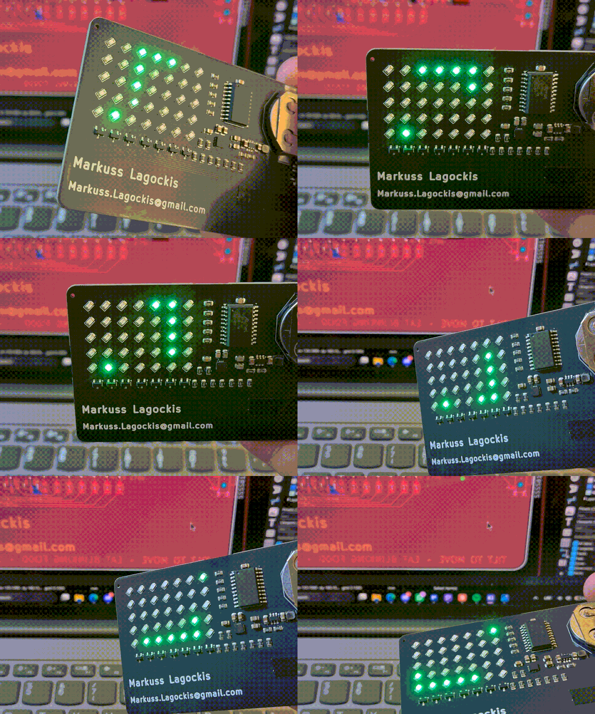
I designed this card to hand out at TechIndustry, the largest tech expo in the Baltics. A paper card gets thrown away. A card that plays Snake gets passed around.
The original idea was a fluid simulation, but on a 7×5 matrix it just looked like random blinking, so it became Snake instead.
| MCU | ATtiny1616 |
| Accelerometer | MMA8451 |
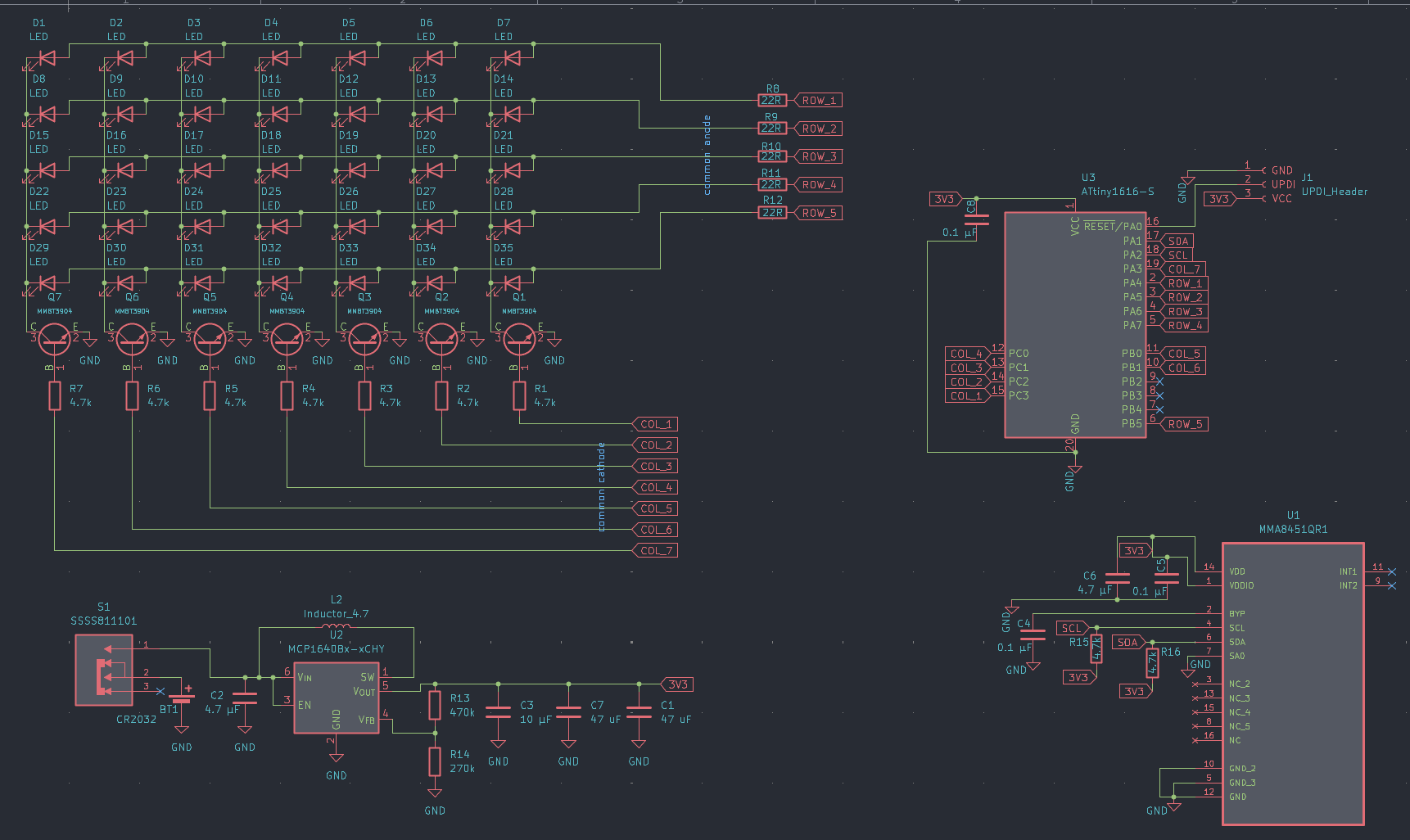
| Power | CR2032 coin cell → MCP1640 boost converter → stable 3.3 V |
| Display | 35 LEDs in a 7×5 multiplexed matrix |
| PCB | 2-layer, credit card size, fabricated and assembled by JLCPCB |
| Cost | ~€6 per card, assembled |
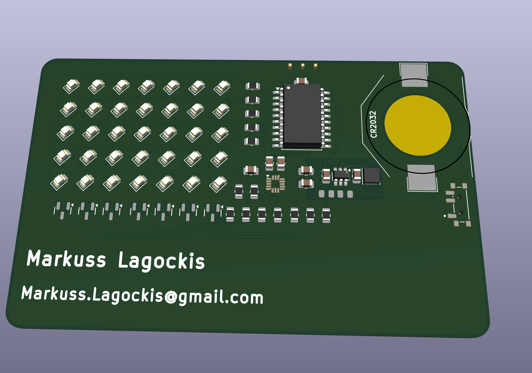
The rows are driven directly from the MCU pins through 22 Ω resistors. The columns are switched by a row of SOT-23 transistors along the bottom of the board. The firmware scans through the columns fast enough that the whole matrix looks lit at once.
The LEDs are rotated 45°. Together with the transistor array underneath, the matrix wiring is some of my cleanest routing work, and it worked on the first try.
Written in the Arduino IDE. The ATtiny1616 is programmed over UPDI, using an Arduino Nano as a makeshift UPDI programmer.
firmware/snake/snake.ino and upload.firmware/
snake/ Arduino sketch
hardware/
kicad/ KiCad project files
schematic.pdf
gerbers/ ready to send to a fab
bom.csv
images/✅ v1 finished. Cards were built, handed out, and work as designed.
🚧 v2 planned. The main change: swap the MMA8451 for a proper IMU. The accelerometer isn't responsive enough, so steering can feel sluggish.
Hardware/Firmware: MIT
| Qty | Value | Footprint | References |
|---|---|---|---|
| 35 | LED | LED_SMD:LED_0805_2012Metric | D1, D2, D10, D11, D12, D13, D14, D15, D16, D17, D18, D19, D20, D21, D22, D23 +19 |
| 9 | 4.7k | Resistor_SMD:R_0805_2012Metric | R1, R2, R3, R4, R5, R6, R7, R15, R16 |
| 7 | MMBT3904 | JLCPCB:Q_SOT-23 | Q1, Q2, Q3, Q4, Q5, Q6, Q7 |
| 5 | 22R | Resistor_SMD:R_0805_2012Metric | R8, R9, R10, R11, R12 |
| 3 | 0.1 µF | Capacitor_SMD:C_0805_2012Metric | C4, C5, C8 |
| 2 | 4.7 µF | Capacitor_SMD:C_0805_2012Metric | C2, C6 |
| 2 | 47 uF | Capacitor_SMD:C_0805_2012Metric | C1, C7 |
| 1 | 10 µF | Capacitor_SMD:C_0805_2012Metric | C3 |
| 1 | 270k | JLCPCB:R_0805 | R14 |
| 1 | 470k | JLCPCB:R_0805 | R13 |
| 1 | ATtiny1616-S | Package_SO:SOIC-20W_7.5x12.8mm_P1.27mm | U3 |
| 1 | CR2032 | Battery:CR2032 | BT1 |
| 1 | Inductor_4.7 | Inductor_SMD:L_APV_ANR3010 | L2 |
| 1 | MCP1640Bx-xCHY | Package_TO_SOT_SMD:SOT-23-6 | U2 |
| 1 | MMA8451QR1 | footprints:QFN50P300X300X100-16N | U1 |
| 1 | SSSS811101 | footprints:SW_SSSS811101Real | S1 |
| 1 | UPDI_Header | Connector:UPDI_P=2.54mm | J1 |
alvestav/alvestav-lee-thesis-project-2025
This is the GitHub repository for the thesis project in computer and electronics engineering by Alvestav and Lee


MitchellStride/Hummingbird-RP2040-Clock-Module
RP2040 RTC Module, highly compatible with JLCPCB's basic SMT components.

It measures 85.6 × 54 mm and has 2 copper layers, 1.6 mm thick.
73 parts, built around the ATTINY1616-SN, MMA8451QR1, MMBT3904 and CR2032. The full list of its parts is on this page, with links to each part's symbol and footprint where PCBKit's library has them.
From the Bumb1eris/PCB_Business_Card repository on GitHub, at the commit this page was made from: the board is hardware/kicad/PersonalPCB_BC.kicad_pcb and its schematic hardware/kicad/PersonalPCB_BC.kicad_sch. PCBKit opens the board in the browser, with nothing to install.
Its repository publishes it under the MIT licence: you may reuse it on that licence's terms (keep the author's notice, and for a copyleft licence share your changes alike).