2 layers55 × 53 mm
ArduinoShield
BioroboticsLab/bb_irflash
Hard- and software for the 2016-style IR flash system of the beesbook project. Original code/hardware design done by hmoenck.
12 partsApache-2.0
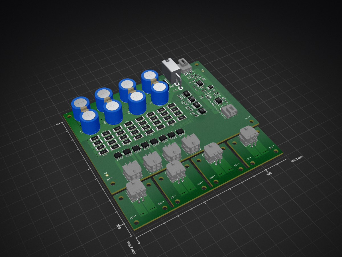
 BioroboticsLab/bb_irflash
Hard- and software for the 2016-style IR flash system of the beesbook project. Original code/hardware design done by hmoenck. Unfortunately, I don't have the original git history available (just a folder on the recording PC..)
HiveCam is an open-source printed circuit board by BioroboticsLab, from the BioroboticsLab/bb_irflash repository on GitHub, published under the Apache-2.0 licence. It is a 2-layer board of 118.3 × 110.7 mm with 133 parts on 45 nets, routed with 504 tracks and 351 vias.
It is built around the 74LVC2G08, LMV358 and NE555DR, with the NTMS4807NR2G-VB and RFD14N05L among its other parts. Its parts include 56 resistors, 14 capacitors, 11 ICs, 11 transistors and 10 diodes.


bb_irflash is a software and hardware layout package. It contains the circuit and board layout for creating infrared flashing devices.
The software is C code written and tested for the Arduino Board Duemilanove. However, it should be easily adjusted to fit any arduino available on the market.
The hardware is designed to be triggered via signal current and powered with 12V. The design contains no protection mechanism whatsoever. So exchanging the resistors and/or LED's enables faster/slower flashing or constant lighting.
The board dimensions are 23mmx51mm, single sided layout. Parts as described in the 'Parts' section enable flashing at 3 Hz and 20 ms duration. Designs come in EAGLE format.
The following Surface-Mount Device (SMD) parts are required for the boards:
See order_examples for further detail, and reference the picture for needed parts.
The board is typically driven at 5V. However, higher light output can be achieved by driving at slightly higher voltages. here are suitable power supply for these voltages. Note that when operating at 6fps and 5msec flashes, one board will draw 1-1.5 amps maximum. Therefore one of these power supplies is sufficient to drive multiple boards.
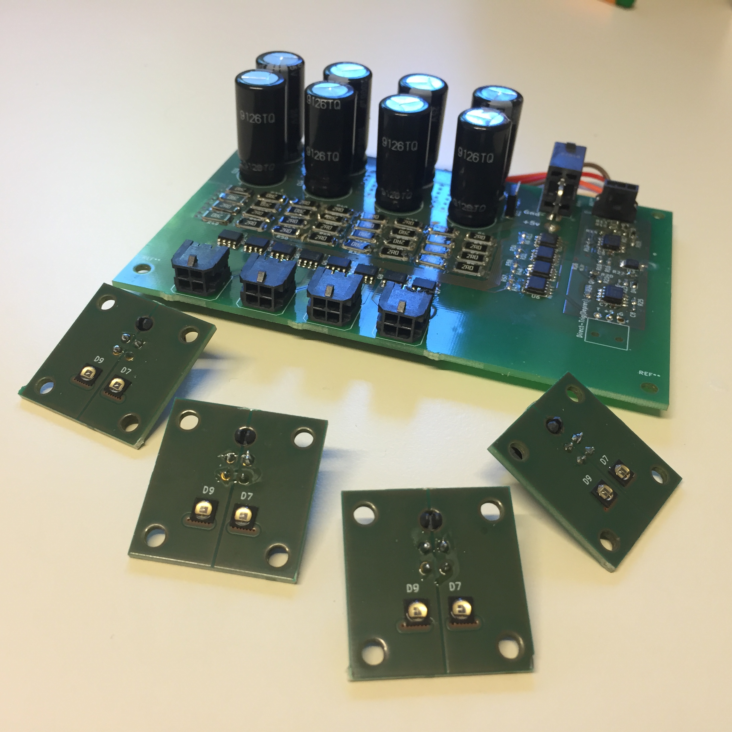
The new IR flash board have the exact same performance as the previous version. The only new part is a better connectivity and a protection circuit. The protection circuit is limiting the impulse duration to 20ms with a pause of 100ms between each pulse for protecting the LED. The power supply should be V ; 6A. To use it just send a step signal of the wanted duration to the trigger pin of the board (The step signal should not be wider than 20ms high and a pause of 100ms should be observe between each pulse)
The files in "board_V2" folder are all the project file in KiCAD format. If you have no interest in redesign, they are not interesting for you.
For fabrication you only need the files in the fabrication folder. The gerber files contained in "fabrication/gerber" are the map of your circuits - You manufacturer would ask for them (likely as a zip file, i.e. gerber.zip containing all folder contents). The subfolder : "fabrication/gerber/drill_file" contain the coordinate of all the holes drilled into the board.
If you want to ask a third party for assembly, you will need the gerber files, the components position files ("Bestückungsplan": assembly_map_top.pdf and assembly_map_bottom.pdf), the Pick&Place placement file (Pick&Place.txt), and the components list (Bill of Materials: BOM.xlsx). The The components position files are in component_position folder (Bottom and top layer). Note that the BOM format can vary in function of your third party company.
The folder order_examples contains two examples for orders placed through Beta Layout with components ordered through Mouser. These are for reference.
| Qty | Value | Footprint | References |
|---|---|---|---|
| 32 | 2 | Resistor_SMD:R_2512_6332Metric | R2, R3, R4, R10, R27, R28, R29, R30, R32, R33, R34, R35, R39, R40, R41, R42 +16 |
| 16 | 10k | Resistor_SMD:R_0603_1608Metric | R1, R6, R11, R12, R13, R16, R18, R21, R22, R26, R31, R36, R47, R48, R57, R58 |
| 8 | 2m | Capacitor_THT:CP_Radial_D12.5mm_P5.00mm | C2, C3, C9, C10, C11, C12, C13, C14 |
| 8 | LED | LED:SFH-4716S | D1, D2, D5, D6, D7, D8, D9, D10 |
| 8 | NTMS4807NR2G | Package_SO:SOIC-8_3.9x4.9mm_P1.27mm | Q1, Q2, Q5, Q6, Q7, Q8, Q9, Q10 |
| 4 | 0.01u | Capacitor_SMD:C_0402_1005Metric | C1, C4, C6, C7 |
| 4 | 22k | Resistor_SMD:R_0603_1608Metric | R14, R17, R23, R24 |
| 4 | LMV358 | Package_SO:SOIC-8_3.9x4.9mm_P1.27mm | U1, U5, U6, U7 |
| 4 | ref | Fiducial:Fiducial_1mm_Mask2mm | U8, U9, U10, U11 |
| 2 | 1u | Capacitor_SMD:C_0402_1005Metric | C5, C8 |
| 2 | 4.7k | Resistor_SMD:R_0603_1608Metric | R15, R20 |
| 2 | DIODE | Diode_SMD:D_0603_1608Metric | D3, D4 |
| 2 | NE555DR | Package_SO:SOIC-8_3.9x4.9mm_P1.27mm | U2, U4 |
| 2 | NSVMMBT2222AM3T5G | Package_TO_SOT_SMD:SOT-723 | Q3, Q4 |
| 1 | 100k | Resistor_SMD:R_0603_1608Metric | R25 |
| 1 | 20k | Resistor_SMD:R_0603_1608Metric | R19 |
| 1 | 74LVC2G08 | Package_SO:TSSOP-8_3x3mm_P0.65mm | U3 |
| 1 | Molex_Mega-Fit_76825-0002_2x01_P5.70mm_Horizontal | Connector_Molex:Molex_Mega-Fit_76825-0002_2x01_P5.70mm_Horizontal | Alim |
| 1 | Molex_Nano-Fit_105313-xx03_1x03_P2.50mm_Horizontal | Connector_Molex:Molex_Nano-Fit_105313-xx03_1x03_P2.50mm_Horizontal | Direct-Trig(Deprec) |
| 1 | RFD14N05L | Package_TO_SOT_THT:TO-251-3_Vertical | Q11 |
The 104 most common of 133 parts.
BioroboticsLab/bb_irflash
Hard- and software for the 2016-style IR flash system of the beesbook project. Original code/hardware design done by hmoenck.


dan-rodrigues/ym2610-pcb
FPGA-based PCB to control a YM2610 sound synthesis chip.

gianlucarenzi/4IDEAdapter
4 ATA/ATAPI IDE Interface for Commodore Amiga 1200 and Amiga 600 computers


derlucae98/spr23e-bmu
Battery Management Unit for the Scuderia Mensa SPR23e/SPR24e electric race car


fl4p/dcdc-parasitics
KiCad → FastHenry extractor for half-bridge power-stage parasitics (commutation-loop L, common-source inductance, gate-loop L/R) → SPICE subckt + SVG schematic

ggarciabaez/titanrio
A RoboRIO-Inspired Expansion board for Robotics. Mostly for funsies + learning.
It measures 118.3 × 110.7 mm and has 2 copper layers, 1.6 mm thick.
133 parts, built around the 74LVC2G08, LMV358, NE555DR and NTMS4807NR2G-VB. The full list of its parts is on this page, with links to each part's symbol and footprint where PCBKit's library has them.
From the BioroboticsLab/bb_irflash repository on GitHub, at the commit this page was made from: the board is board_V2/HiveCam.kicad_pcb. PCBKit opens the board in the browser, with nothing to install.
Its repository publishes it under the Apache-2.0 licence: you may reuse it on that licence's terms (keep the author's notice, and for a copyleft licence share your changes alike).