Skip to the content
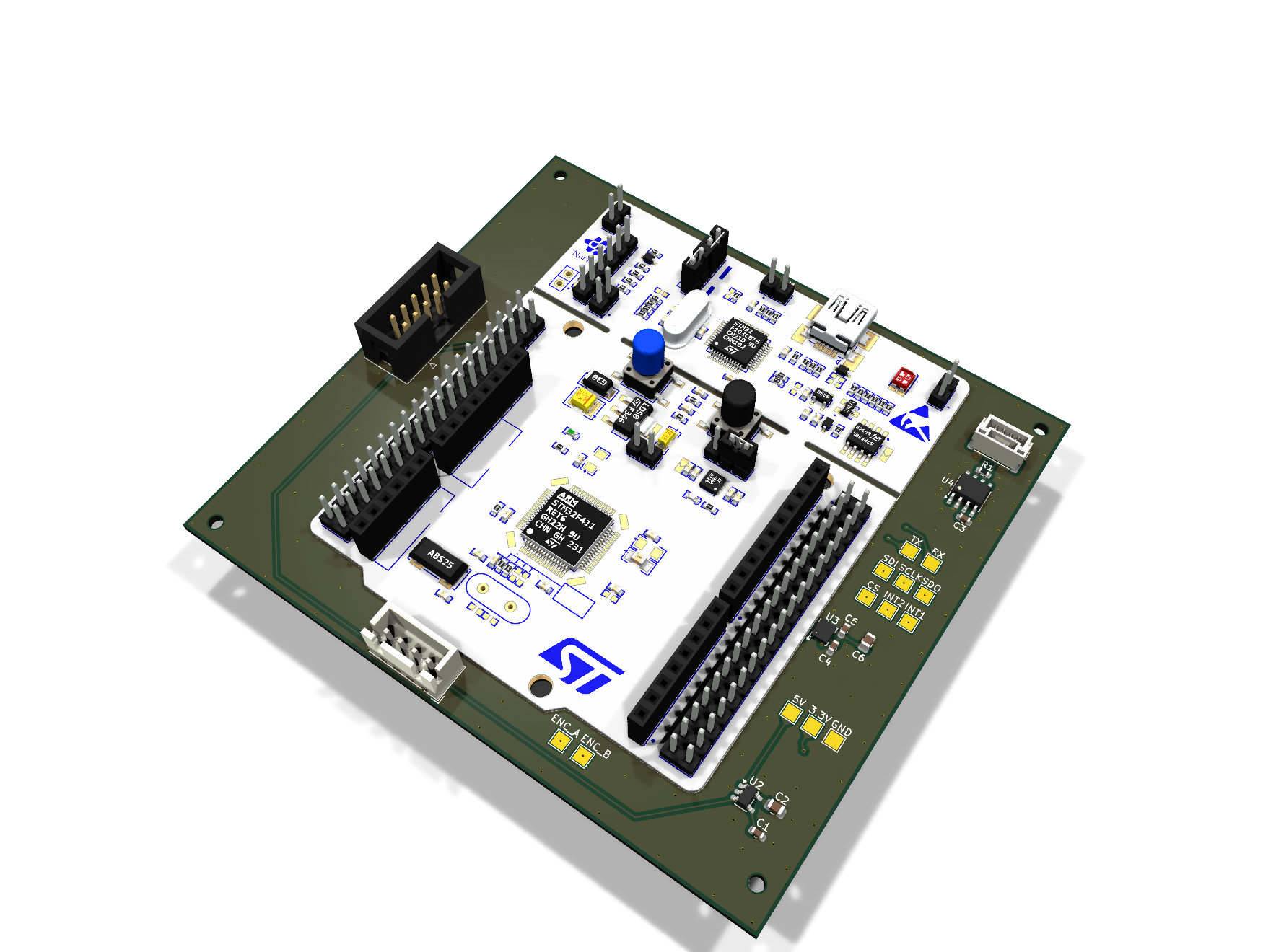
4 layers50 × 50 mmTwo axis balancing carrier mcu version, the printed circuit board in 3D

Two axis balancing carrier mcu version

BenjaminMeyerEE/Two-Axis_Balancing_Robot1

A robot that balances in pitch and roll. The two axes use different hardware: pitch runs a brushless motor through a VESC over CAN, roll runs a brushed motor through an H-bridge on a custom power board.

Size
50 × 50 mm
Copper layers
4
Thickness
1.6 mm
Parts
58
Nets
71
Pads
227
Tracks, vias
302, 39
Pours
2
Routed
Yes
KiCad
KiCad 10.0 (file 20260206)
Created
31 May 2026
Updated
23 Oct 2026

Overview

Two axis balancing carrier mcu version is an open-source printed circuit board by BenjaminMeyerEE, from the BenjaminMeyerEE/Two-Axis_Balancing_Robot repository on GitHub. It is a 4-layer board of 50 × 50 mm with 58 parts on 71 nets, routed with 302 tracks and 39 vias.

It is built around the SN65HVD230D, ICM-42688-P and MIC5219-3.3YM5. Its parts include 23 capacitors, 7 resistors, 5 connectors, 4 ICs and 2 diodes. It belongs with the STM32 boards of this library.

Main components

3

README

README.md

Two-Axis Balancing Robot

A robot that balances in pitch and roll. The two axes use different hardware: pitch runs a brushless motor through a VESC over CAN, roll runs a brushed motor through an H-bridge on a custom power board. Both close around an STM32G474 and an ICM-42688-P IMU on a custom carrier board. Two custom 4-layer boards, designed in KiCad.
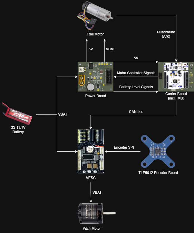
Electrical architecture

Specifications

ParameterValue
AxesPitch and roll, separate drive hardware
ControllerSTM32G474RET6 (Nucleo-G474RE on the carrier board)
IMUICM-42688-P over SPI, both interrupt lines broken out
Pitch driveBrushless motor via VESC, commanded over CAN
Pitch feedbackTLE5012 magnetic encoder, SPI to the VESC
Roll driveBrushed motor via TB6612FNG dual H-bridge
Roll feedbackQuadrature encoder into the carrier board
Battery3S LiPo, 11.1 V nominal
Carrier board101.6 × 92.9 mm, 4-layer
Power board50.0 × 42.9 mm, 4-layer

Status

Both custom PCBs are designed and the electrical architecture is laid out. Mechanical design is partly finished.

I simulated the pitch axis in Simulink first, and that's what pushed me away from PID and toward LQR. Wheel position and tilt are coupled through the dynamics, so tuning them as separate loops meant the two kept fighting each other. Full state feedback made more sense than trying to manage that interaction by hand.

What I'm working on now is the model itself: deriving the equations of motion with Lagrangian mechanics, linearizing about the upright equilibrium, and designing a discrete-time LQR with Bryson's rule setting the cost weights. That work is all in MATLAB.

Repository layout

PathContents
hardware/two_axis_balancing_carrier/Carrier board KiCad project
hardware/two_axis_balancing_power/Power board KiCad project
docs/Architecture diagram, board renders, layer plots

Hardware

Both boards are 4-layer. Every copper layer below is plotted from the top and unmirrored, so features line up between layers.

Carrier board

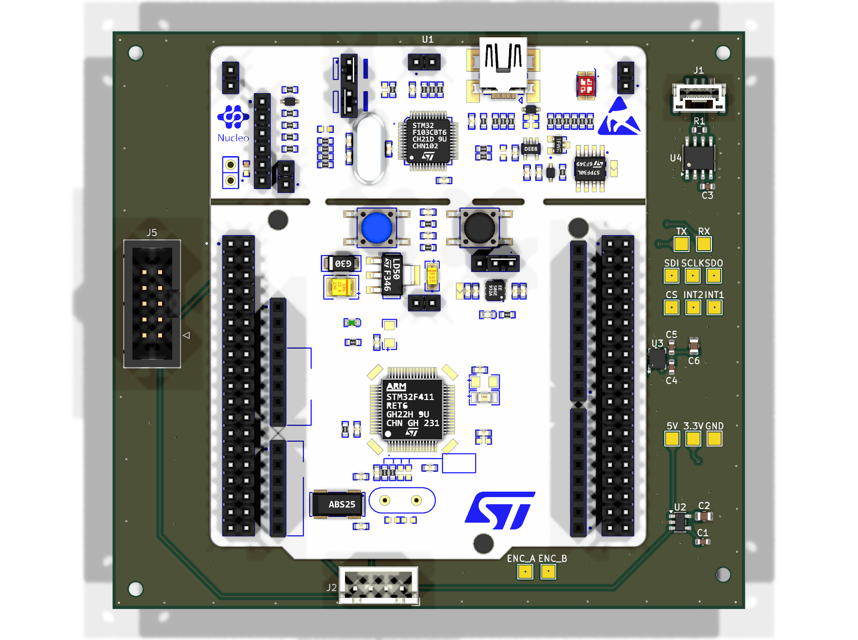
101.6 × 92.9 mm. Holds the Nucleo-G474RE and everything the control loop reads.

Carrier boardCarrier board, top

The ICM-42688-P is on SPI (CS, SCLK, SDI, SDO) with INT1 and INT2 brought out, so the loop can run off data-ready rather than polling. An SN65HVD230 with 120 Ω termination puts the board on the CAN bus to the VESC. A MIC5219-3.3 makes the 3.3 V rail from the 5 V coming off the power board.

Roll encoder channels come in here on ENC_A / ENC_B. Motor commands (AIN1, AIN2, PWMA, STBY) and the battery signals go back to the power board over a 2×5 IDC ribbon. There are 13 test points, and the SPI, UART, encoder and rail pads are all labelled on the silkscreen for bring-up.

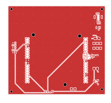
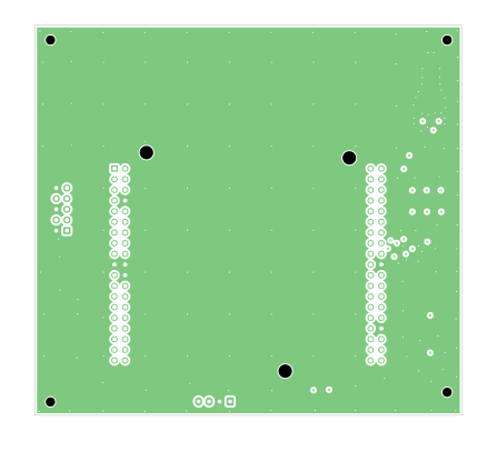
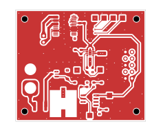
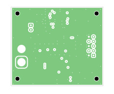
F.CuIn1.Cu
F.CuIn1.Cu
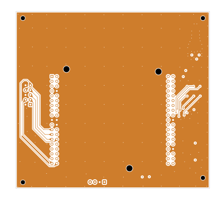
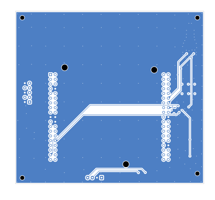
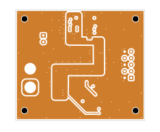
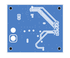
In2.CuB.Cu
In2.CuB.Cu

Power board

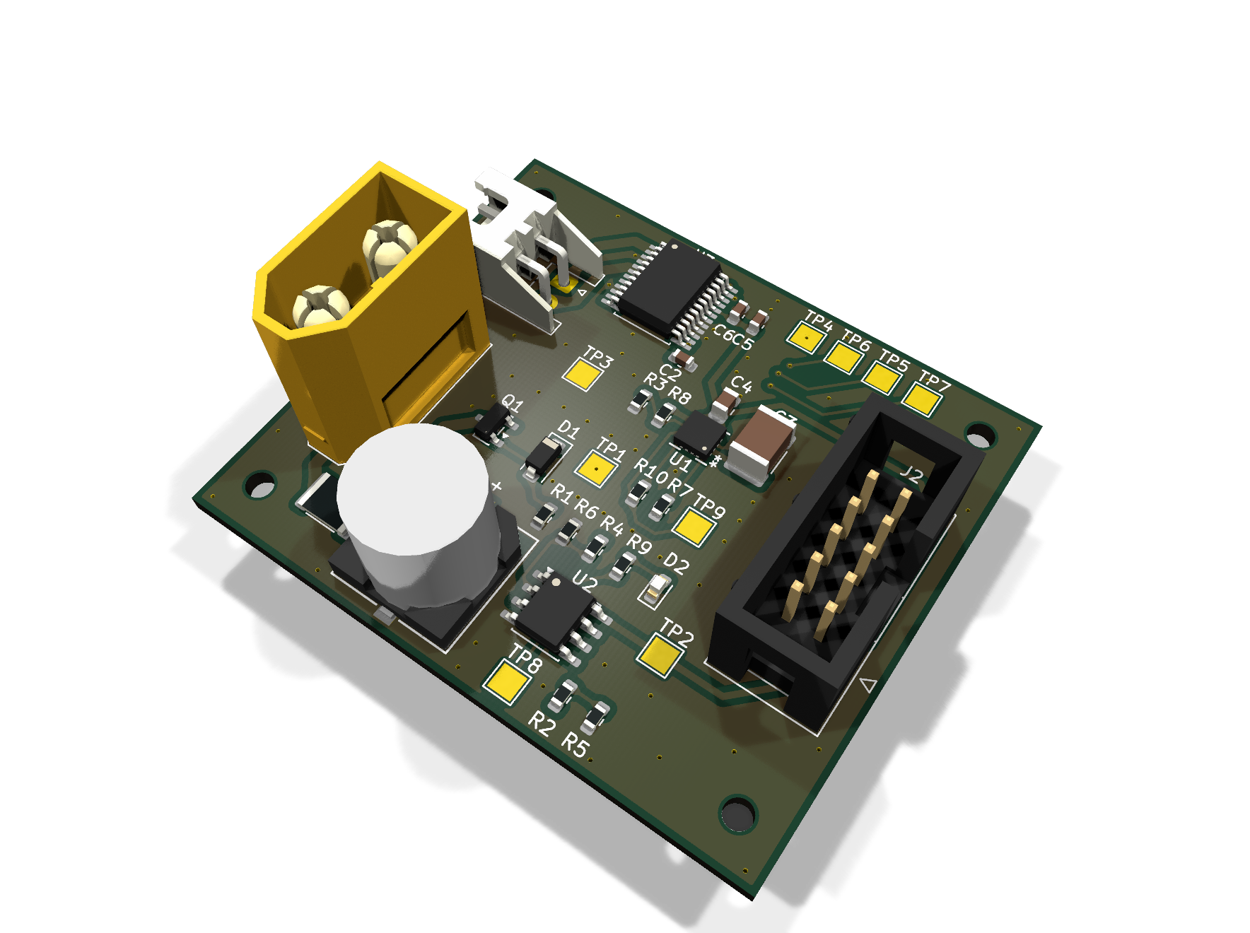
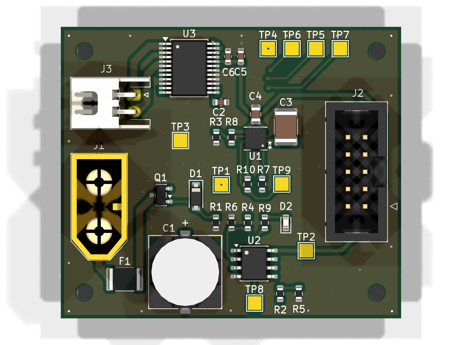
50.0 × 42.9 mm. Takes the battery in and handles everything that touches VBAT.

Power boardPower board, top

Battery comes in on an XT60, behind a 3 A fuse, an AO3401A P-channel MOSFET for reverse polarity, and a 10 V zener. An RPL-1.0-R module makes the 5 V rail and reports Buck_PG back to the MCU. A TB6612FNG dual H-bridge drives the roll motor on MOTOR_P / MOTOR_N.

Battery monitoring is done on this board rather than in firmware. A divider gives BAT_LEV, an LM393 compares it against BAT_REF, and BAT_LOW goes back to the carrier board. The MCU sees both the raw level and a latched low flag.

F.CuIn1.Cu
F.CuIn1.Cu
In2.CuB.Cu
In2.CuB.Cu

Connectors

BoardRefConnectorCarries
PowerJ1XT603S battery in
PowerJ3JST XH, 2-pinRoll motor out (MOTOR_P / MOTOR_N)
PowerJ2IDC 2×5To the carrier board
CarrierJ5IDC 2×5To the power board
CarrierJ2JST XH, 4-pinRoll encoder (ENC_A, ENC_B, 5 V, GND)
CarrierJ1JST GH, 3-pinCAN to the VESC (CANH, CANL, GND)

The 2×5 ribbon is the only link between the two boards. It carries the 5 V rail and ground, the four TB6612FNG control lines (AIN1, AIN2, PWMA, STBY) and the two battery monitoring signals (BAT_LEV, BAT_LOW). VBAT never reaches the carrier board, which only ever sees 5 V.

Parts

58
QtyValueFootprintReferences
12TestPointTestPoint:TestPoint_Pad_D1.0mmTP1, TP2, TP3, TP4, TP6, TP7, TP8, TP9, TP10, TP11, TP12, TP13
11100nFCapacitor_SMD:C_0603_1608MetricC1, C3, C9, C10, C11, C12, C13, C14, C17, C20, C23
310kRResistor_SMD:R_0603_1608MetricR5, R6, R7
2100pFCapacitor_SMD:C_0603_1608MetricC21, C22
212pFCapacitor_SMD:C_0603_1608MetricC18, C19
21kRResistor_SMD:R_0603_1608MetricR3, R4
21uFCapacitor_SMD:C_0805_2012MetricC15, C16
22.2uFCapacitor_SMD:C_0805_2012MetricC4, C6
2FerriteBeadCapacitor_SMD:C_0603_1608MetricFB1, FB2
2LEDLED_SMD:LED_0603_1608MetricD1, D2
2TestPointTestPoint:TestPoint_Keystone_5015_Micro_MiniTP5, TP14
110nFCapacitor_SMD:C_0603_1608MetricC2
1120RResistor_SMD:R_0603_1608MetricR1
11uFCapacitor_SMD:C_0603_1608MetricC5
14.7uFCapacitor_SMD:C_0805_2012MetricC8
1470pFCapacitor_SMD:C_0603_1608MetricC7
147RResistor_SMD:R_0603_1608MetricR2
18MHzCrystal:Crystal_SMD_3225-4Pin_3.2x2.5mmY1
1Conn_01x04Connector_JST:JST_XH_B4B-XH-A_1x04_P2.50mm_VerticalJ3
1Conn_01x04Connector_JST:JST_GH_BM04B-GHS-TBT_1x04-1MP_P1.25mm_VerticalJ1
1Conn_02x05Connector_IDC:IDC-Header_2x05_P2.54mm_VerticalJ2
1Conn_02x08_Odd_EvenConnector_PinHeader_2.54mm:PinHeader_2x08_P2.54mm_VerticalJ5
1Conn_ST_STDC14Connector_PinHeader_1.27mm:PinHeader_2x07_P1.27mm_VerticalJ4
1ICM-42688-PICM:LGA14_2P5X3X0P91_TDKU2
1MIC5219-3.3YM5Package_TO_SOT_SMD:SOT-23-5U3
1SN65HVD230Package_SO:SOIC-8_3.9x4.9mm_P1.27mmU1
1STM32G474RETxPackage_QFP:LQFP-64_10x10mm_P0.5mmU4

More from BenjaminMeyerEE/Two-Axis_Balancing_Robot

2
  • 4 layers50 × 42.9 mmTwo axis balancing power, the printed circuit board in 3D

    Two axis balancing power

    BenjaminMeyerEE/Two-Axis_Balancing_Robot

    A robot that balances in pitch and roll. The two axes use different hardware: pitch runs a brushless motor through a VESC over CAN, roll runs a brushed motor through an H-bridge on a custom power board.

    42 parts1
  • 4 layers101.6 × 92.9 mmTwo axis balancing carrier, the printed circuit board in 3D

    Two axis balancing carrier

    BenjaminMeyerEE/Two-Axis_Balancing_Robot

    A robot that balances in pitch and roll. The two axes use different hardware: pitch runs a brushless motor through a VESC over CAN, roll runs a brushed motor through an H-bridge on a custom power board.

    31 parts1

Similar boards

  • 8 layers34 × 54.8 mmH7-Beast, the printed circuit board in 3D

    H7-Beast

    FBIopeningUPP/H7-Beast

    Just a flight controller

    84 parts
  • 2 layers39.4 × 42.5 mmLeanLine, the printed circuit board in 3D

    LeanLine

    FBIopeningUPP/LeanLine

    A.T.L.A.S. is a bare-metal system it revolves around track-day with ur superbikes. It calculates ur lean angles, track positioning using GPS, and lap times at a frequency of 100Hz, it logs the data directly to your…

    55 parts
  • 4 layers65 × 45 mmControls carier board, the printed circuit board in 3D

    Controls carier board

    pipipipi2002/embedded-controls

    An attempt to understand control theories using accelerometer, gyroscopes, magnetometer and barometer.

    77 partsGPL-3.0
  • 6 layers133.1 × 133.1 mmAERIS H743-PCB, the printed circuit board in 3D

    AERIS H743-PCB

    7903555032/AERIS-H743-PCB

    A 6-layer STM32H743-based embedded development and flight-control/data-logging PCB designed as a practical hardware-design and PCB-layout project.

    114 parts1
  • 6 layers40.6 × 40.5 mmFlight Controller, the printed circuit board in 3D

    Flight Controller

    desanv01/Flight-Controller-V2

    STM32H743 controller: regulated power, signal-only ESC, neutral ArduPilot firmware, manufacturing data and engineering history.

    169 partsCERN-OHL-S-2.0
  • 6 layers51 × 53.5 mmCustom fc rat, the printed circuit board in 3D

    Custom fc rat

    Ekta-Gupta27/custom-flight-controller-pcb

    Custom flight controller PCB designed in KiCad with STM32F7, multiple sensors, CAN, USB, telemetry, PWM and IO interfaces.

    122 parts
  • 6 layers36 × 36 mmStm32h743-px4, the printed circuit board in 3D

    Stm32h743-px4

    DataFlux-Robot/fluxpcb

    全自动AI电路设计流水线: 需求→选型→原理图→PCB→验收仿真→固件,六环节门禁闭环 | Six-stage automated circuit design pipeline with machine-checkable verification gates

    22 parts1Apache-2.0
  • 2 layers80 × 50 mmThermal Camera, the printed circuit board in 3D

    Thermal Camera

    Circuit-Digest/MLX90640-Thermal-Camera

    An Open Source Thermal Imaging IR camera that you can build yourserlf

    66 parts94

Questions

How big is the Two axis balancing carrier mcu version PCB?

It measures 50 × 50 mm and has 4 copper layers, 1.6 mm thick.

What parts does the Two axis balancing carrier mcu version use?

58 parts, built around the SN65HVD230D, ICM-42688-P and MIC5219-3.3YM5. The full list of its parts is on this page, with links to each part's symbol and footprint where PCBKit's library has them.

Where can I download the Two axis balancing carrier mcu version KiCad files?

From the BenjaminMeyerEE/Two-Axis_Balancing_Robot repository on GitHub, at the commit this page was made from: the board is hardware/two_axis_balancing_carrier_mcu_version/two_axis_balancing_carrier_mcu_version/two_axis_balancing_carrier_mcu_version.kicad_pcb and its schematic hardware/two_axis_balancing_carrier/two_axis_balancing_carrier.kicad_sch. PCBKit opens the board in the browser, with nothing to install.

Can I use the Two axis balancing carrier mcu version design in my own project?

Its repository states no licence, so its author keeps all rights: ask BenjaminMeyerEE before reusing the design.