

2 layers55.5 × 57 mm
Mobility aid
TF2113/mobility-aid
An embedded style system designed to assist visually impaired individuals using real-time proximity sensing and traffic light recognition.
20 parts
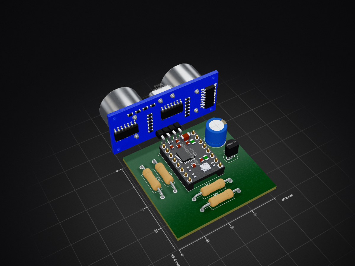
 AlexDom513/autoDistance
FPGA project to automatically control the position of a cart on a ramp
AutoDistance is an open-source printed circuit board by AlexDom513, from the AlexDom513/autoDistance repository on GitHub, published under the MIT licence. It is a 2-layer board of 40.6 × 39.4 mm with 8 parts on 17 nets, routed with 37 tracks and 0 vias.
It is built around the HC-SR04 and PN2222A. Its parts include 4 resistors, 2 ICs, 1 capacitor and 1 transistor.
The goal of this project is to implement a simple PID controller using a FPGA. (1) and (2) served as the inspiration for this project. Note that a FPGA is being used as an exercise. It is much more convenient to use a microcontroller for this application.
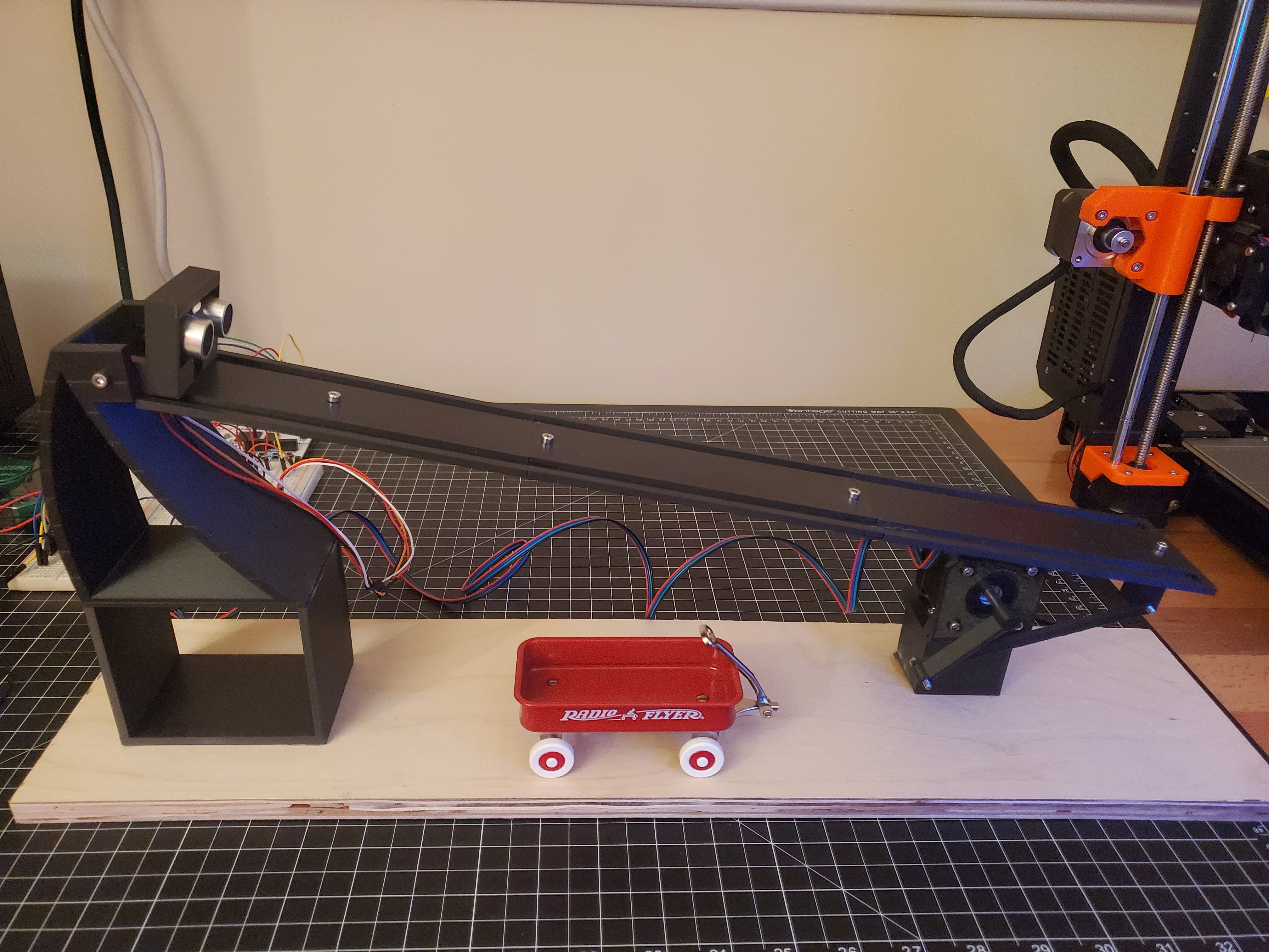
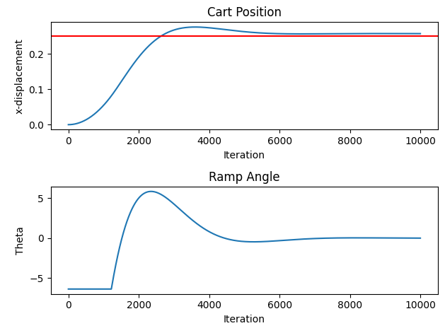
Before starting to implement the PID controller in hardware, a Python script was used to understand the algorithm and the system it would be used in. The script was set up in such a way that the user can specify variables like the set-point, the PID gains, and the cart mass.
A simulation then shows how the cart position is affected by the changing angle of a ramp:
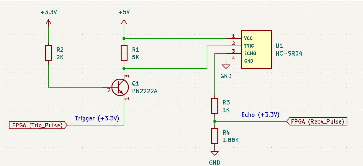
The PulseController module is responsible for interacting with the ultrasonic sensor. According to the datasheet, the FPGA must send a 10 microsecond trigger pulse. The sensor the sends eight 40 kHz pulses and detects whether there is a returned pulse. If there is a returned pulse, the time of high output from the sensor is proportional to the distance detected.
After obtaining the cart distance in the PulseController module, the PIDController module is used to compute an appropriate ramp angle so that the cart will be directed towards the ramp's center. Proportional gain (P) is a function of where the cart is located along the ramp. Integral gain (I) continues to increase while the cart's observed position is different from the target position. Derivative gain (D) is dependent on how quickly the cart is approaching the target position. A state machine is used to jump between states that contain different computations (error, gains, ramp angle, scaling/saturation).
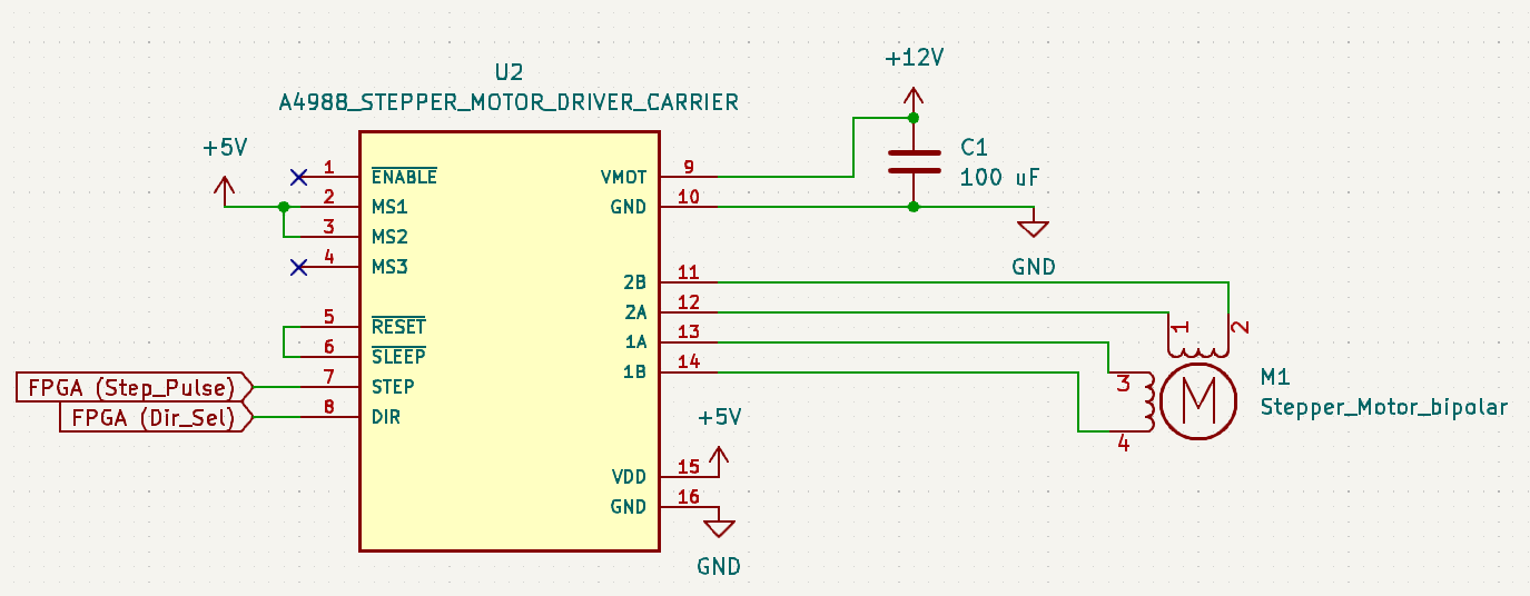
Whenever a new ramp angle is computed, it is passed to the StepperController module. This module translates the value into physical movement by the stepper motor attached to the ramp. Two state machines are used to implement this functionality (Stepper State Machine & Pulse State Machine). The Stepper State Machine has a counter that is used to track the position of the stepper motor. The counter is set to 0 during startup. We then monitor whether the output from PIDController is greater than or less than the current value of the counter. Depending on the condition, we will either have the stepper motor increment or decrement from its current position. A signal that controls the motor's direction is set low/high and the Pulse State Machine is used to send trigger pulses to a A4988 motor controller. The stepper motor finally increments or decrements in the desired direction.
Note: toggled controlled signals (via switches) are NOT shown
Converts the +3.3V Trig_Pulse signal to +5V logic. Signal is connected to ultrasonic sensor (HC-SR04). The sensor outputs a +5V signal which is converted back to +3.3V before being passed to the FPGA.
Connects control signals (Step_Pulse, Dir_Sel) from the FPGA to the stepper control board (A4988). Since the design is using 1/8 microstepping, MS1 and MS2 are also tied to +5V.
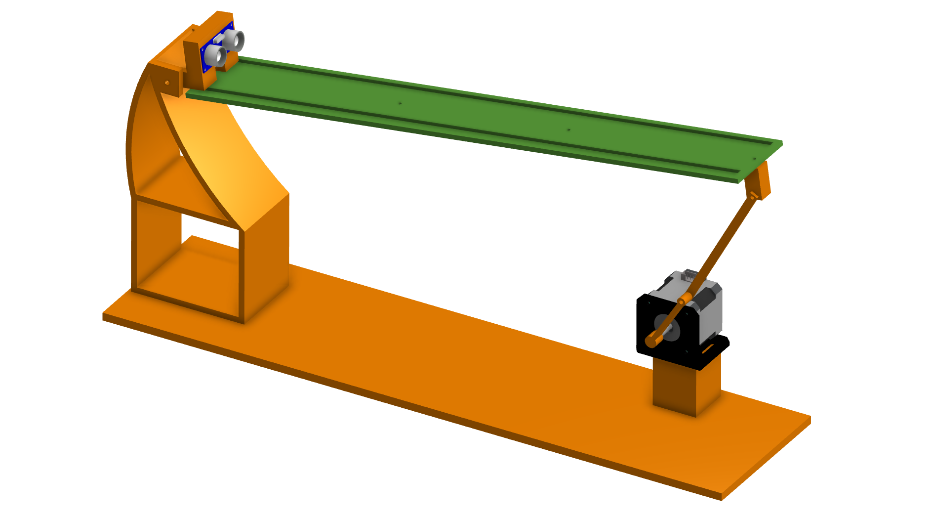
This was my first serious attempt at creating a 3D model! All parts were printed using PLA on a PRUSA MK3.
| Qty | Value | Footprint | References |
|---|---|---|---|
| 1 | 1.88K | Resistor_THT:R_Axial_DIN0309_L9.0mm_D3.2mm_P15.24mm_Horizontal | R4 |
| 1 | 100 uF | Capacitor_THT:CP_Radial_D8.0mm_P2.50mm | C1 |
| 1 | 1K | Resistor_THT:R_Axial_DIN0309_L9.0mm_D3.2mm_P15.24mm_Horizontal | R3 |
| 1 | 2K | Resistor_THT:R_Axial_DIN0309_L9.0mm_D3.2mm_P15.24mm_Horizontal | R2 |
| 1 | 5K | Resistor_THT:R_Axial_DIN0309_L9.0mm_D3.2mm_P15.24mm_Horizontal | R1 |
| 1 | A4988_STEPPER_MOTOR_DRIVER_CARRIER | 1-myComponents:MODULE_A4988_STEPPER_MOTOR_DRIVER_CARRIER | U2 |
| 1 | HC-SR04 | 1-myComponents:XCVR_HC-SR04 | U1 |
| 1 | PN2222A | Package_TO_SOT_THT:TO-92_Inline | Q1 |
TF2113/mobility-aid
An embedded style system designed to assist visually impaired individuals using real-time proximity sensing and traffic light recognition.

kennySzhucheng/EnvMonitor
🌡️ 智能环境监测站 | STM32F103C8T6 + FreeRTOS + ESP8266 | 温湿度/光照/测距/OLED菜单/ThingSpeak上云 | 从裸机到RTOS到KiCad PCB全流程


NikolaiRadke/Noko_2
The do-it-yourself Arduino-based Noko monster. Version 2 with PCB and 3D printed casing.

billtsol/Maze
This project demonstrates how to use an Arduino board, IR sensors, and a motor driver shield to create a maze-solving robot.

c-lydia/ESP-ROS2
A tiny robot with IMU (MPU5060) and an ultrasonic sensor (HC-SR04), running on micro-ROS, communicating over UDP.

dbrgn/crazyflie2-hcsr04
Ultrasonic sensor (HC-SR04) extension board for the Crazyflie 2.0

YousefAliAicha/aegis-embedded-system
Networked rotating ultrasonic radar system built on the Deneyap Kart 1A (ESP32-S3), with a real-time web dashboard served directly from the board.
It measures 40.6 × 39.4 mm and has 2 copper layers, 1.6 mm thick.
8 parts, built around the HC-SR04 and PN2222A. The full list of its parts is on this page, with links to each part's symbol and footprint where PCBKit's library has them.
From the AlexDom513/autoDistance repository on GitHub, at the commit this page was made from: the board is schematic-files/autoDistance.kicad_pcb and its schematic schematic-files/autoDistance.kicad_sch. PCBKit opens the board in the browser, with nothing to install.
Its repository publishes it under the MIT licence: you may reuse it on that licence's terms (keep the author's notice, and for a copyleft licence share your changes alike).