2 layers47.6 × 48.2 mm

 Alex-Riviello/power_supply_mk1
Power supply created during ELE3000 - Personal project at Polytechnique Montreal (2017). The voltage is controlled by a PWM signal generated by a EFM8 Silicon Labs microcontroller.
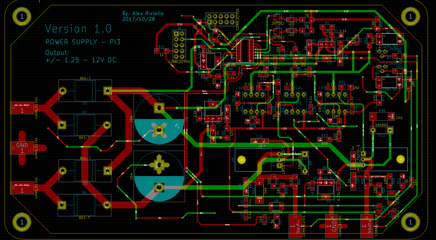
Power Supply Rev01 is an open-source printed circuit board by Alex-Riviello, from the Alex-Riviello/power_supply_mk1 repository on GitHub. It is a 2-layer board of 188 × 106.7 mm with 113 parts on 53 nets, routed with 662 tracks and 71 vias.
It is built around the EFM8BB10F8G-A-SOIC16R, OPA241PA and 6A1-T, with the FOD817BS among its other parts. Its parts include 41 resistors, 32 capacitors, 12 ICs, 10 diodes and 8 connectors. It belongs with the power boards and the Silicon Labs (EFR32, EFM) boards of this library.


Power supply created during ELE3000 - Personal project at Polytechnique Montreal (2017).
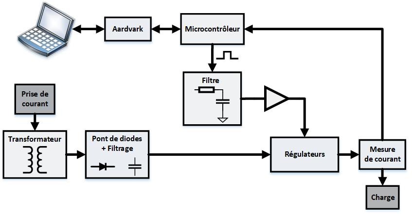
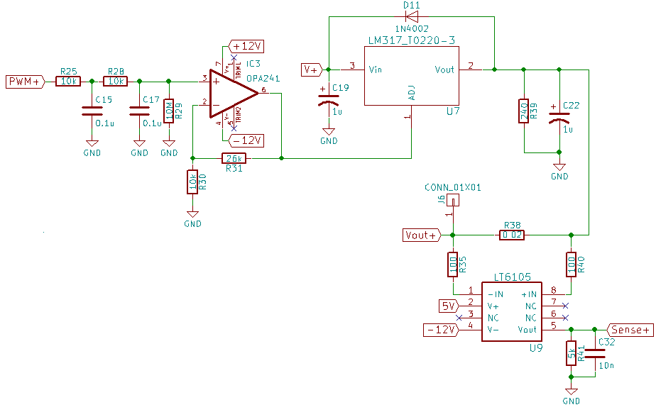
The voltage is controlled by a PWM signal generated by a EFM8 Silicon Labs microcontroller. The signal is filtered and injected into the adjust pin of a LM337 and LM317 to generate a variable positive and negative voltage (got the idea from the EEVBlog#221 https://www.youtube.com/watch?v=CIGjActDeoM&t=860s).
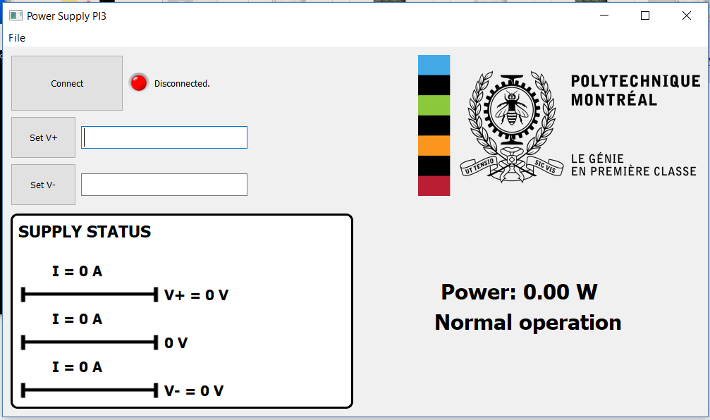
To communicate with the microcontroller, I used an Aardvark (USB to I2C Host Adapter). The voltage was set and the current was measured in real-time. Everything was displayed on a GUI made with PyQt.
TODO: Translate to english.
The PCB was designed using KiCAD. The KiCAD project can be found in the ./kicad_psu_mk1 directory.
NOTE: This was one of my first PCB designs. I tried using many through-hole components to test them on a breadboard.
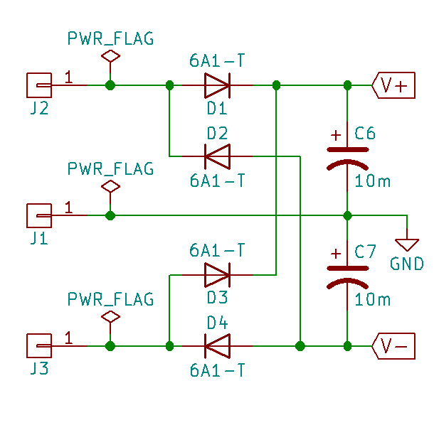
A simple diode bridge was used to rectify the voltage coming out of the transformer.
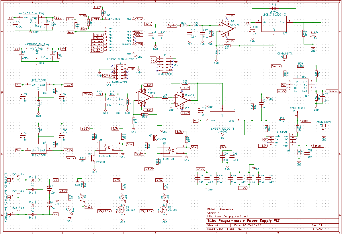
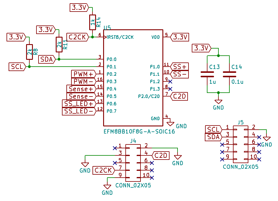
The EFM8BB1 microcontroller was used for this project. I chose this MCU since I had a couple laying around. A laptop communicates with the chip via I2C (and a USB to I2C adapter). I2C was used since it's a simple protocol that be used with a Raspberry Pi. The MCU also sends a PWM signal to the voltage regulators to modulate the output voltage. 2 ADCs are used to measure the voltage drop across a very small resistor to detect the current flowing through the outputs.
The voltage is controlled with a PWM signal which is filtered and amplified. An LM317 is used for the positive voltage and a LM337 is used for the negative voltage.
The python GUI used is illustrated below. The voltage could be set and read in real-time. The code can be found in ./python_code. However, the hc file is not included (Aardvark interface), PyQt4 is no longer supported and the code runs in Python2.
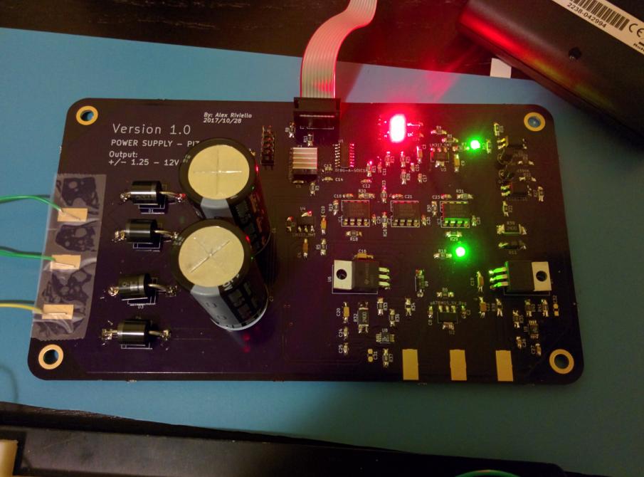
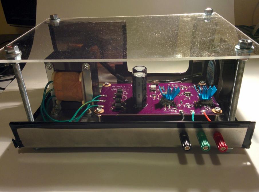
Overall, the PSU could provide upto 1.5 A of current at +/-2V to +/- 12.5V. The final circuit looked like this:
| Qty | Value | Footprint | References |
|---|---|---|---|
| 17 | 0.1u | Capacitors_SMD:C_0805_HandSoldering | C5, C11, C12, C14, C15, C17, C18, C21, C23, C24, C25, C26, C27, C28, C29, C30 +1 |
| 8 | 10k | Resistors_SMD:R_1206_HandSoldering | R13, R15, R19, R23, R25, R26, R28, R30 |
| 8 | 1u | Capacitors_Tantalum_SMD:CP_Tantalum_Case-A_EIA-3216-18_Hand | C3, C4, C9, C10, C16, C19, C20, C22 |
| 6 | CONN_01X01 | Wire_Pads:SolderWirePad_single_SMD_5x10mm | J1, J2, J3, J6, J7, J8 |
| 4 | 100 | Resistors_SMD:R_1206_HandSoldering | R33, R35, R36, R40 |
| 4 | 570 | Resistors_SMD:R_1206_HandSoldering | R7, R10, R12, R22 |
| 4 | 6A1-T | Diodes_THT:D_P600_R-6_P20.00mm_Horizontal | D1, D2, D3, D4 |
| 4 | LED | LEDs:LED_0805_HandSoldering | D5, D6, D7, D8 |
| 3 | OPA241 | OPA241:DIL08 | IC1, IC2, IC3 |
| 2 | 0.02 | Resistors_SMD:R_1206_HandSoldering | R34, R38 |
| 2 | 0.33u | Capacitors_SMD:C_0805_HandSoldering | C1, C2 |
| 2 | 1.1k | Resistors_SMD:R_1206_HandSoldering | R1, R2 |
| 2 | 10M | Resistors_SMD:R_1206_HandSoldering | R18, R29 |
| 2 | 10m | Capacitors_THT:CP_Radial_D22.0mm_P10.00mm_SnapIn | C6, C7 |
| 2 | 10n | Capacitors_SMD:C_0805_HandSoldering | C31, C32 |
| 2 | 120 | Resistors_SMD:R_1206_HandSoldering | R4, R5 |
| 2 | 180 | Resistors_SMD:R_1206_HandSoldering | R16, R27 |
| 2 | 1N4002 | Diodes_THT:D_DO-41_SOD81_P7.62mm_Horizontal | D9, D11 |
| 2 | 1k | Resistors_SMD:R_1206_HandSoldering | R6, R14 |
| 2 | 2.7k | Resistors_SMD:R_1206_HandSoldering | R9, R21 |
| 2 | 240 | Resistors_SMD:R_2512_HandSoldering | R32, R39 |
| 2 | 26k | Resistors_SMD:R_1206_HandSoldering | R20, R31 |
| 2 | 2N7002 | TO_SOT_Packages_SMD:SOT-23 | Q3, Q5 |
| 2 | 2k | Resistors_SMD:R_1206_HandSoldering | R8, R11 |
| 2 | 5k | Resistors_SMD:R_1206_HandSoldering | R37, R41 |
| 2 | 70 | Resistors_SMD:R_1206_HandSoldering | R17, R24 |
| 2 | CONN_02X05 | Pin_Headers:Pin_Header_Straight_2x05_Pitch2.54mm | J4, J5 |
| 2 | FOD817BS | FOD817BS:SOIC254P1016X385-4N | Q2, Q6 |
| 2 | LT6105 | Housings_SSOP:MSOP-8_3x3mm_Pitch0.65mm | U8, U9 |
| 1 | 1u | Capacitors_SMD:C_0805_HandSoldering | C13 |
| 1 | 2N3904 | 2N3904:TO92 | Q1 |
| 1 | 2N3906 | 2N3906:TO92D | Q4 |
| 1 | 620 | Resistors_SMD:R_1206_HandSoldering | R3 |
| 1 | EFM8BB10F8G-A-SOIC16 | EFM8BB10F8G-A-SOIC16:SOIC127P600X175-16N | U5 |
| 1 | LM317_SMT | SOT230P700X180-4N:SOT230P700X180-4N | U3 |
| 1 | LM317_T0220-3 | TO_SOT_Packages_THT:TO-220-3_Horizontal | U7 |
| 1 | LM337_SMT | SOT230P700X180-4N:SOT230P700X180-4N | U4 |
| 1 | LM337_T0220-3 | TO_SOT_Packages_THT:TO-220-3_Horizontal | U6 |
| 1 | uA78M05_5V_Reg | SOT230P700X180-4N:SOT230P700X180-4N | U2 |
| 1 | uA78M33_3.3V_Reg | SOT230P700X180-4N:SOT230P700X180-4N | U1 |
The 109 most common of 113 parts.


blu006/blu_BOB_and_MISC
My breakout boards and miscellaneous boards


It measures 188 × 106.7 mm and has 2 copper layers, 1.6 mm thick.
113 parts, built around the EFM8BB10F8G-A-SOIC16R, OPA241PA, 6A1-T and FOD817BS. The full list of its parts is on this page, with links to each part's symbol and footprint where PCBKit's library has them.
From the Alex-Riviello/power_supply_mk1 repository on GitHub, at the commit this page was made from: the board is kicad_psu_mk1/Power_Supply_Rev01.kicad_pcb. PCBKit opens the board in the browser, with nothing to install.
Its repository states no licence, so its author keeps all rights: ask Alex-Riviello before reusing the design.