2 layers26.5 × 34.4 mm
PicoLoaderNSB
makeo/PicoLoader
A cheap and easy to install modchip for the Nintendo GameCube!
45 parts320GPL-2.0

 Alan-GIRAUDON/VGAutumn
VGAutumn is a RP2040 VGA joystick PCB. This board allows to play different game using its VGA output and its inputs (joystick, buttons).
VGAutumn is an open-source printed circuit board by Alan-GIRAUDON, from the Alan-GIRAUDON/VGAutumn repository on GitHub, published under the MIT licence. It is a 2-layer board of 108.5 × 61 mm with 72 parts on 65 nets, routed with 624 tracks and 180 vias.
It is built around the RP2040, W25Q128JVSIQ and XC6206P332MR, with the RKJXV122400R among its other parts. Its parts include 24 resistors, 17 capacitors, 5 connectors, 4 switches and 3 ICs. It belongs with the RP2040 boards of this library.


VGAutumn is a RP2040 VGA joystick PCB. This board allows to play different game using its VGA output and its inputs (joystick, buttons).
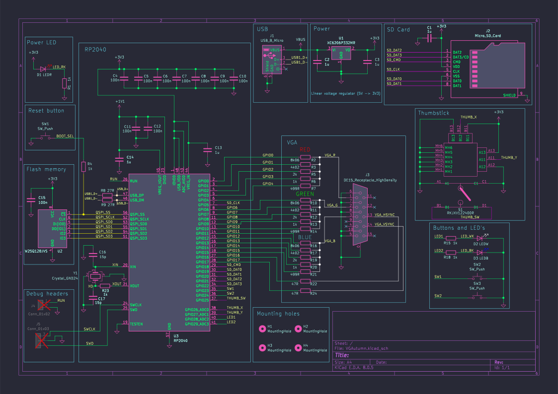
The PCB is a two layer board with single-sided assembly, the thinnest trace is 0.2 mm and the vias have a 0.7 mm diameter ring and a 0.3 mm hole. The USB traces are as short and as thick as possible to be as close as possible to the 90 $\Omega$ impedance of the JLCPCB two-layer board stackup.
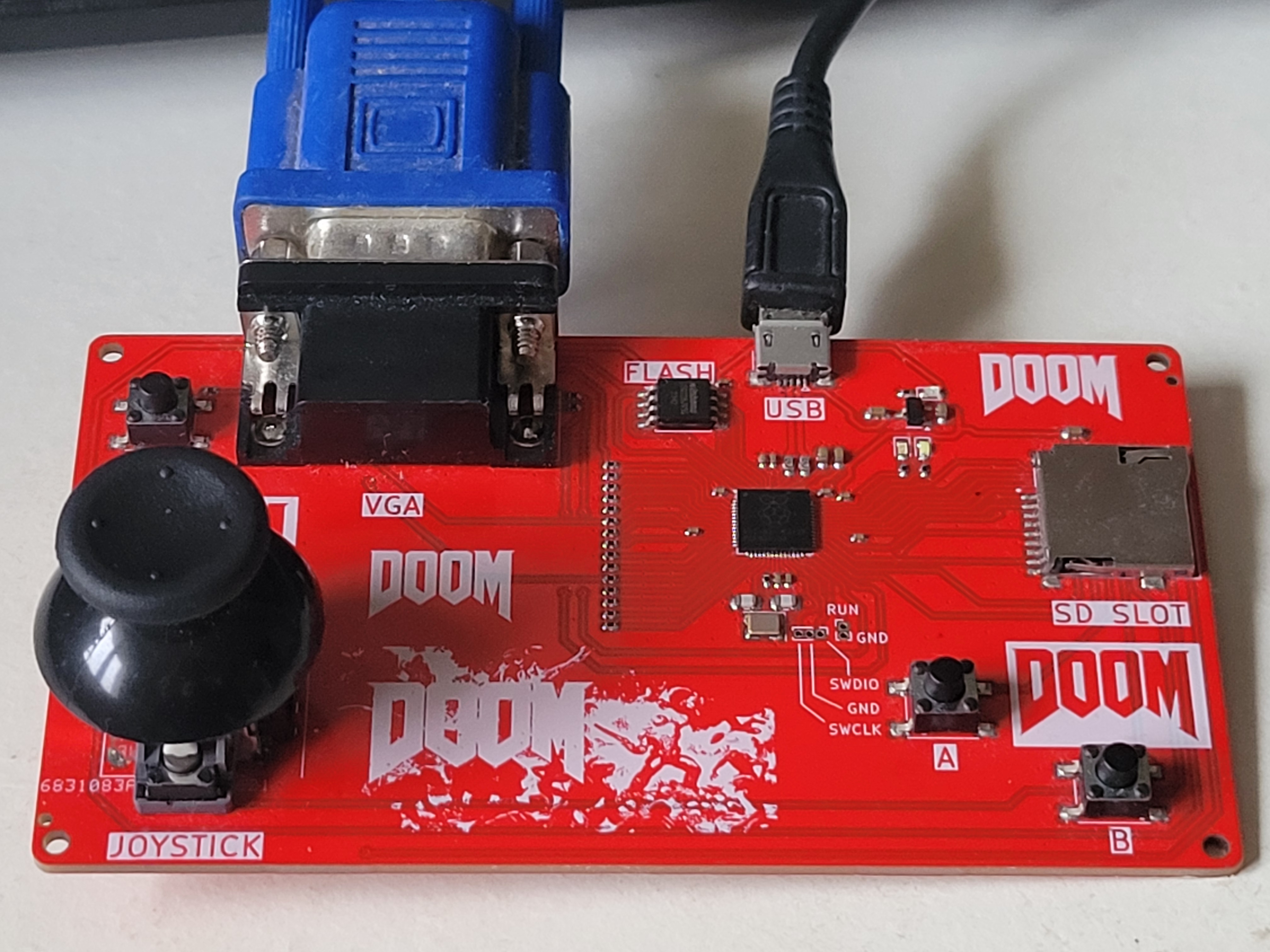
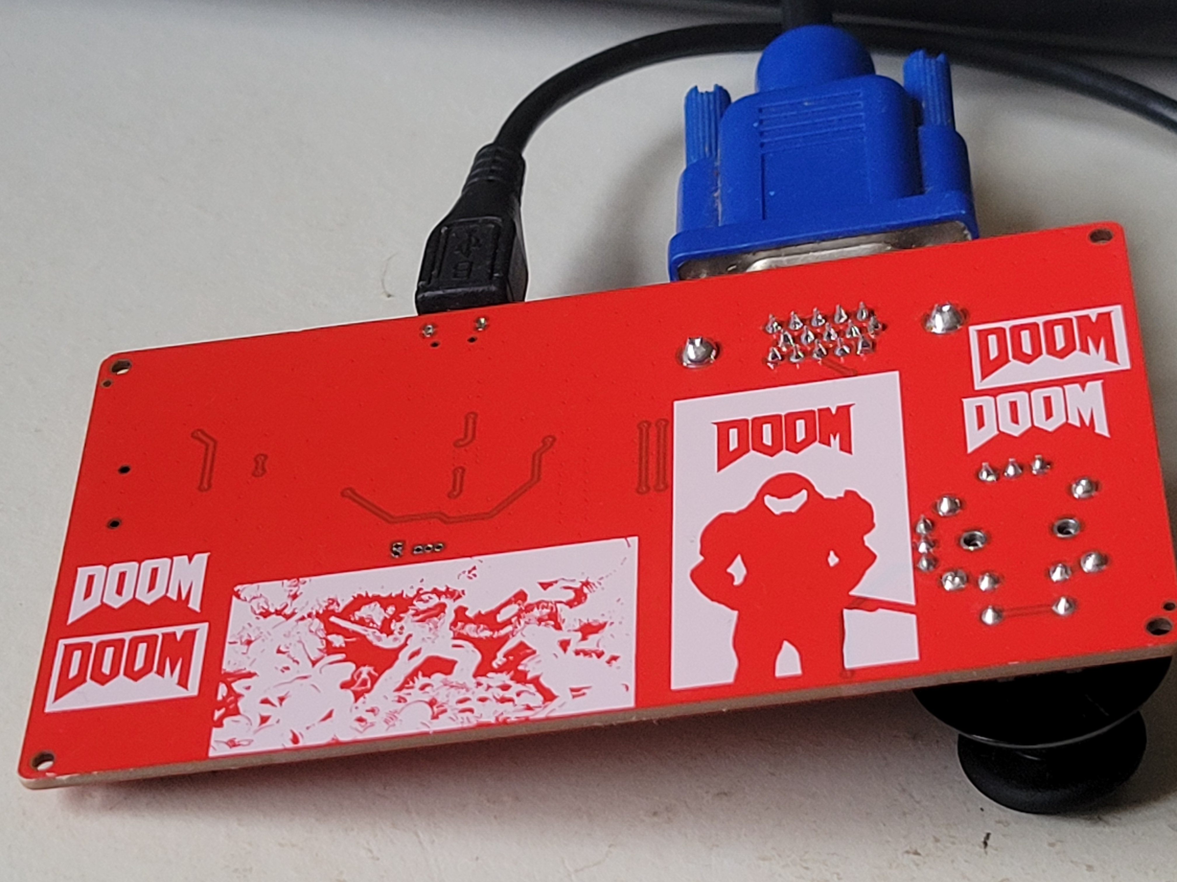
The board can be programmed in Python through the Thonny IDE, in C/C++ with CMake (VS Code, NVIM) and even (not tested) with the Arduino IDE.
The "pico-playgrounds" and "pico-examples" given by Raspberry are a great way to test the VGA output and the Joystick.
To run Doom on the board, we can use the RP2040-doom by kilograham (congratulations to him for this amazing work), the first release of "doom1-usb.uf2" work out of the box because the board use the default VGA pins.
Note : To make Doom responds to Joystick and buttons inputs, you need to modify the code in the pico folder.
| Qty | Value | Footprint | References |
|---|---|---|---|
| 11 | LOGO | LOGO | G***, G***, G***, G***, G***, G***, G***, G***, G***, G***, G*** |
| 10 | 100n | Capacitor_SMD:C_0402_1005Metric | C4, C5, C6, C7, C8, C9, C10, C11, C12, C15 |
| 8 | 1k | Resistor_SMD:R_0402_1005Metric | R1, R4, R6, R13, R15, R18, R20, R23 |
| 5 | 1u | Capacitor_SMD:C_0603_1608Metric | C1, C2, C3, C13, C14 |
| 4 | MountingHole | MountingHole:MountingHole_2.2mm_M2 | H1, H2, H3, H4 |
| 3 | 2k | Resistor_SMD:R_0402_1005Metric | R5, R12, R19 |
| 3 | 499R | Resistor_SMD:R_0402_1005Metric | R7, R14, R21 |
| 3 | 4k02 | Resistor_SMD:R_0402_1005Metric | R3, R11, R17 |
| 3 | 8k06 | Resistor_SMD:R_0402_1005Metric | R2, R10, R16 |
| 3 | SW_Push | Button_Switch_SMD:SW_Push_1P1T_NO_6x6mm_H9.5mm | SW1, SW2, SW3 |
| 2 | 15p | Capacitor_SMD:C_0805_2012Metric | C16, C17 |
| 2 | 27R | Resistor_SMD:R_0603_1608Metric | R8, R9 |
| 2 | 47R | Resistor_SMD:R_0402_1005Metric | R22, R24 |
| 1 | Conn_01x02 | Connector_PinHeader_1.00mm:PinHeader_1x02_P1.00mm_Vertical | J4 |
| 1 | Conn_01x03 | Connector_PinHeader_1.00mm:PinHeader_1x03_P1.00mm_Vertical | J5 |
| 1 | Crystal_GND24 | Crystal:Crystal_SMD_SeikoEpson_FA238-4Pin_3.2x2.5mm | Y1 |
| 1 | DE15_Receptacle_HighDensity | VGAutumn:VGA | J3 |
| 1 | LEDB | LED_SMD:LED_0603_1608Metric | D3 |
| 1 | LEDR | LED_SMD:LED_0603_1608Metric | D1 |
| 1 | LEDW | LED_SMD:LED_0603_1608Metric | D2 |
| 1 | Micro_SD_Card | VGAutumn:GCT_MEM2075-00-140-01-A | J2 |
| 1 | RKJXV122400R | VGAutumn:RKJXV122400R | S1 |
| 1 | RP2040 | Package_DFN_QFN:QFN-56-1EP_7x7mm_P0.4mm_EP3.2x3.2mm | U3 |
| 1 | USB_B_Micro | Connector_USB:USB_Micro-B_XKB_U254-051T-4BH83-F1S | J1 |
| 1 | W25Q128JVS | Package_SO:SOIC-8_5.23x5.23mm_P1.27mm | U2 |
| 1 | XC6206P332MR | Package_TO_SOT_SMD:SOT-23-3 | U1 |
makeo/PicoLoader
A cheap and easy to install modchip for the Nintendo GameCube!

sd2psx/pcb
The PCB must be produced in 0.8mm thickness. Production files are provided under the "Releases" tab. These do not include the through-hole OLED module.

deltabeard/DBGC
A Game Boy cartridge using the Raspberry Pi RP2040 with RTC and MBC support.

ergomechstore/rp2040-bento
The RP2040-bento is a breakout board for the RP2040 MCU.

xiphonics/picoTracker-pcb
Buy the official kit at xiphonics store # Trademark Notice


ramonimbao/SpaceInvadersFRL
An F-rowless TKL keyboard case, plate, and PCB that uses the HiTek Series 725 switches.

It measures 108.5 × 61 mm and has 2 copper layers, 1.6 mm thick.
72 parts, built around the RP2040, W25Q128JVSIQ, XC6206P332MR and RKJXV122400R. The full list of its parts is on this page, with links to each part's symbol and footprint where PCBKit's library has them.
From the Alan-GIRAUDON/VGAutumn repository on GitHub, at the commit this page was made from: the board is VGAutumn.kicad_pcb and its schematic VGAutumn.kicad_sch. PCBKit opens the board in the browser, with nothing to install.
Its repository publishes it under the MIT licence: you may reuse it on that licence's terms (keep the author's notice, and for a copyleft licence share your changes alike).