2 layers82.3 × 35.5 mm
 wlhlm/fc980c-controller20
Leopold FC980C replacement keyboard controller
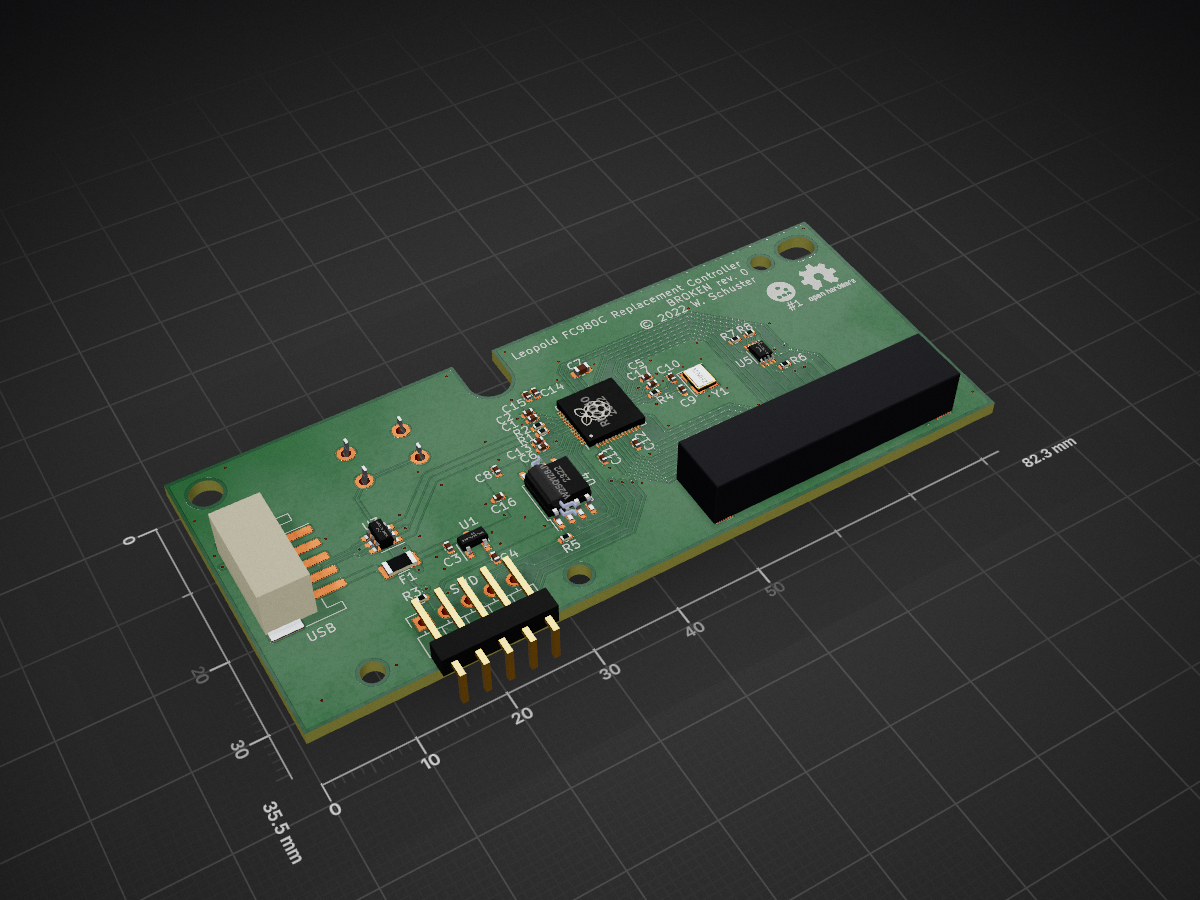
Fc980c controller is an open-source printed circuit board by wlhlm, from the wlhlm/fc980c-controller repository on GitHub. It is a 2-layer board of 82.3 × 35.5 mm with 38 parts on 58 nets, routed with 351 tracks and 89 vias.
It is built around the RP2040, W25Q128JVSIQ and PCA9306DC, with the USBLC6-2SC6 and XC6206P332MR among its other parts. Its parts include 17 capacitors, 8 resistors, 5 ICs, 3 connectors and 1 switch. It belongs with the keyboards and input boards and the RP2040 and STM32 boards of this library.


This PCB replaces the controller of the Leopold FC980C keyboard to allow running alternate firmware, especially open source firmware such as QMK. This project relies heavily on the prior reverse engineering work done by hasu (aka tmk) and collaborators.
This is the first PCB I have designed and as such I suspect this will have many areas that can be improved. I am very much looking forward to hearing feedback about this design, if you think something can be improved please open an issue and let me know. I will list my reasons for various design choices below, as well as an errata section to list shortcomings of the current design that I am aware of.
 (the resistor hand-soldered to the connector is due to a flaw of the revision 1
design, which has been fixed in revision 2)
Specs:
Why would anyone want a replacement keyboard controller for the FC980C? In case the original controller gets fried, the lack of controller replacement from the manufacturer would otherwise mean tossing the whole (expensive) keyboard. This board enables the usage of Free and Open Source firmware to replace the proprietary stock firmware. Running alternate firmware allows enabling hardware features not accessible through the original controller such as actuation point adjustments, not to mention the plethora of software features enabled by QMK for example.
If you have received this controller fully assembled, your next step will be
firmware setup. Check the firmware/ directory in this repository.
In case you still have to solder on the connectors, see the assembly section below.
This PCB is intended to be manufactured and assembled by JLCPCB, except for the connectors and a button on the back of the board, which most likely have to be soldered on the PCB by hand.
The button (labled BOOT0) is through-hole and easily soldered by hand. Make sure to place it on the bottom side, i.e. opposite side of the MCU, where the DIP switches are on the original controller board.
The connector for the USB board (USB) is though-hole and can be hand-soldered.
The SWD header is optional and can be left unsoldered.
The connector labeled KEYBOARD is only available for surface mounting and unfortunately not available at JLC for assembly (at least at the time of design). Hand-soldering is a bit more challenging for this connector. Make sure to use a healthy dose of flux and fine gauge solder wire.
While the PCB itself can be manufactured by a number of PCB houses, component
selection and SMD assembly is made with JLCPCB in mind. The
jlcpcb/production_files folder for each revision should include the necessary
BOM and CPL files in addition to the Gerbers. The board parameters are specified
in the PCB design file (the main parameters being a board thickness of 1.6mm and
2 copper layers). For the option "Remove Order Number", you can select "Specify
a location".
This board is compatible with JLC's "Economic PCBA" option. For option "Assembly Side", choose "Top Side" and under "Tooling holes" you can specify "Added by Customer".
The EEPROM (U4) and accompanying decoupling capacitor (C6) are optional. The board should work without those populated.
The specific component selection is tailored to what was available at JLCPCB at the time of design. While things like the capacitors and resistors can be easily substituted, Larger ICs such as the USB protection, fuse, 3.3V regulator, and MCU have not been evaluated for alternative parts.
The USB and KEYBOARD connectors interface with the existing connectors used in the FC980C and cannot be substituted.
I don't intend to sell this controller PCB by myself and as such everyone who is interested in the design is meant to order this directly from JLC for themselves. As such, I've tried to minimize cost for low quantity production runs. JLC has the concept of extended and basic parts where the former incurs a one-time setup fee per production rund per component as those components require additional labor for setting up the pick and place machines with the respective components. I've tried to keep the number of extended components as low as possible.
The main requirements for the microcontroller were 5V tolerance and good compatibility with QMK. I also tried to take pricing and availability for the foreseeable future into account. My choice fell on the STM32F401 that is used in the cheap "Blackpill" development boards. It is well supported by QMK and is also used in another Topre controller board project that replaces the PCB of the Realforce R1 TKL keyboards.
The 5V fuse and USB protection components have been carried forward from the original RP2040-based design (revision 1) and have been taken from this RP2040 design guide.
USB trace width has been calculated using the KiCad built-in calculator following a guide on the Digikey blog. The wide traces are caused by the board design having two layers and a thickness of 1.6mm. This is most likely overkill as the bandwidth requirements are very low for a keyboard. Reviewing a number of other boards, none were using USB-specific trace widths.
None found thus far.
The SWD header is unusable since SWDIO has been routed to the wrong pin on the MCU (PA15 instead of PA13). This has no impact on the actual controller functionality. Fixed in revision 2.
Unfortunately, the KEY_STATE pin is missing a 5V pull-up resistor. A manual
fix (such as soldering a 10k resistor between the KEY_STATE [pin 14] and 5V
pins on the KEYBOARD connector) is necessary. Fixed in revision 2.

Updates SWD pinout to correctly use PA13 on the MCU for SWDIO instead of PA15.
Minor position adjustments to drill holes.
Adds 5V pull-up resistor to KEY_STATE line.
Removes I2C level shifter to simplify BOM.
Sample tested and working: not yet—it is recommended to enable the options "Confirm Production file" and "Confirm Parts Placement" when ordering from JLC

First design that has a chance to actually work in the FC980C. Switch to a STM32F401 microcontroller. This MCU allows saving a couple of components compared to the RP2040, such as USB termination resistors and external flash.
One notable addition compared to the previous revision is an optional 64Kb EEPROM.
Sample tested and working: tested and issues identified (see Errata section), working with the suggested manual fixes

The first version of this PCB uses a RP2040 controller. Unfortunately, the FC980C electronics rely on the MCU being 5V tolerant. I have noticed this only while triple checking the design just before submitting it for manufacturing. The RP2040 is not 5V tolerant and would require level shifters on many I/O lines. Because of that I decided to scrap the design and start anew, but since the board design was pretty much complete, I'm including it in this repository for posterity.
Sample tested and working: no
This replacement controller relies heavily on the prior reverse engineering work of the keyboard community, including uncovering schematics for the similar Leopold FC660C that were submitted to the FCC that helped me figure out the I/O voltage requirements. In particular, I want to thank hasu (aka tmk) who created a FC980C replacement controller based on the ATmega32u4 MCU, publishing schematics and an open source firmware implementation for tmk that has been ported to QMK.
Thanks to Toocanzs#5098 from the QMK Discord for helping me with the crystal load capacitor calculation.
The PCB has been designed using KiCad 6 and production files have been exported using Bouni's JLCPCB tools plugin.
These are various resources, that helped me designing my first PCB:
This helped with the software matrix scanning implementation:
This helped me immensensly in figuring out the FC980C-specific hardware requirements for the FC980C controller:
Copyright © 2022 Wilhelm Schuster
This PCB design is licensed under the CERN-OHL-S v2. See the LICENSE file in each of the revision folders for the license text. This license is strongly reciprocal and is similar in spirit to the GPL, but specifically focuses on hardware.
The firmware portion of this project is licensed under GPL-2-or-later in accordance with the QMK project. See the LICENSE file in the firmware folder for the license text.
| Qty | Value | Footprint | References |
|---|---|---|---|
| 10 | 100nF | Capacitor_SMD:C_0402_1005Metric | C5, C6, C8, C11, C12, C13, C14, C15, C16, C17 |
| 4 | 1uF | Capacitor_SMD:C_0402_1005Metric | C1, C2, C3, C4 |
| 3 | 1k | Resistor_SMD:R_0402_1005Metric | R3, R4, R5 |
| 2 | 10k | Resistor_SMD:R_0402_1005Metric | R7, R8 |
| 2 | 27R | Resistor_SMD:R_0402_1005Metric | R1, R2 |
| 2 | 27pF | Capacitor_SMD:C_0402_1005Metric | C9, C10 |
| 1 | 10uF | Capacitor_SMD:C_0603_1608Metric | C7 |
| 1 | 12MHz | Crystal:Crystal_SMD_3225-4Pin_3.2x2.5mm | Y1 |
| 1 | 200k | Resistor_SMD:R_0402_1005Metric | R6 |
| 1 | 500mA | Fuse:Fuse_1206_3216Metric | F1 |
| 1 | BOOTSEL | Button_Switch_THT:SW_PUSH_6mm | SW1 |
| 1 | KEYBOARD | additional:HRS_DF14_20P | J3 |
| 1 | LOGO | additional:logo | G*** |
| 1 | Logo_Open_Hardware_Small | Symbol:OSHW-Logo2_7.3x6mm_SilkScreen | LOGO1 |
| 1 | PCA9306DC | Package_SO:VSSOP-8_2.3x2mm_P0.5mm | U5 |
| 1 | RP2040 | sleep-lib:RP2040-QFN-56 | U2 |
| 1 | SWD | Connector_PinHeader_2.54mm:PinHeader_1x05_P2.54mm_Horizontal | J1 |
| 1 | USB | Connector_JST:JST_PH_S5B-PH-SM4-TB_1x05-1MP_P2.00mm_Horizontal | J2 |
| 1 | USBLC6-2SC6 | Package_TO_SOT_SMD:SOT-23-6 | U3 |
| 1 | W25Q128JVS | Package_SO:SOIC-8_5.23x5.23mm_P1.27mm | U4 |
| 1 | XC6206P332MR | Package_TO_SOT_SMD:SOT-23 | U1 |

thegamer3-141/16bit_transistor_computer
A 16-bit computer built from discrete transistors, inspired by Ben Eater's famous 8-bit breadboard computer project.


makeo/PicoLoader
A cheap and easy to install modchip for the Nintendo GameCube!

sd2psx/pcb
The PCB must be produced in 0.8mm thickness. Production files are provided under the "Releases" tab. These do not include the through-hole OLED module.

deltabeard/DBGC
A Game Boy cartridge using the Raspberry Pi RP2040 with RTC and MBC support.

ergomechstore/rp2040-bento
The RP2040-bento is a breakout board for the RP2040 MCU.

xiphonics/picoTracker-pcb
Buy the official kit at xiphonics store # Trademark Notice

ramonimbao/SpaceInvadersFRL
An F-rowless TKL keyboard case, plate, and PCB that uses the HiTek Series 725 switches.
It measures 82.3 × 35.5 mm and has 2 copper layers, 1.6 mm thick.
38 parts, built around the RP2040, W25Q128JVSIQ, PCA9306DC and USBLC6-2SC6. The full list of its parts is on this page, with links to each part's symbol and footprint where PCBKit's library has them.
From the wlhlm/fc980c-controller repository on GitHub, at the commit this page was made from: the board is rev0/fc980c-controller.kicad_pcb and its schematic rev0/fc980c-controller.kicad_sch. PCBKit opens the board in the browser, with nothing to install.
Its repository states no licence, so its author keeps all rights: ask wlhlm before reusing the design.