
2 layers23 × 120 mm

 AYUSH-pro-grammer/hermes
For my Hermes project, I made a compact handheld motion detector based on the MPU6050 IMU, a XIAO RP2040 microcontroller, and a 0.96" OLED screen.
Hermas is an open-source printed circuit board by AYUSH-pro-grammer, from the AYUSH-pro-grammer/hermes repository on GitHub. It is a 2-layer board of 38 × 53 mm with 8 parts on 35 nets, routed with 76 tracks and 1 via.
It is built around the MPU-6050. Its parts include 3 capacitors, 3 ICs and 2 resistors. It belongs with the RP2040 boards of this library.
For my Hermes project, I made a compact handheld motion detector based on the MPU6050 IMU, a XIAO RP2040 microcontroller, and a 0.96" OLED screen. The board reads acceleration and rotational values of the sensor and outputs it on the screen.
I decided to use the MPU6050 because I wanted to know more about IMUs and how to make a device which detects motion. Also, since the MPU6050 communicates using I²C protocol, it helped me understand such concepts as pull-up resistors, datasheets, decoupling capacitors, and PCB designing.
The circuit board is controlled by the XIAO RP2040. Both the MPU6050 and the OLED display are connected through the I²C bus, meaning that they use common SDA and SCL pins.
The MPU6050 is connected as follows:
The OLED screen is connected to the same I²C bus:
Two 4.7kΩ pull-up resistors were used for the SDA and SCL pins in order to follow the I²C specification.
Also, the MPU6050 employs decoupling capacitors in order to stabilize the voltage and minimize noise.
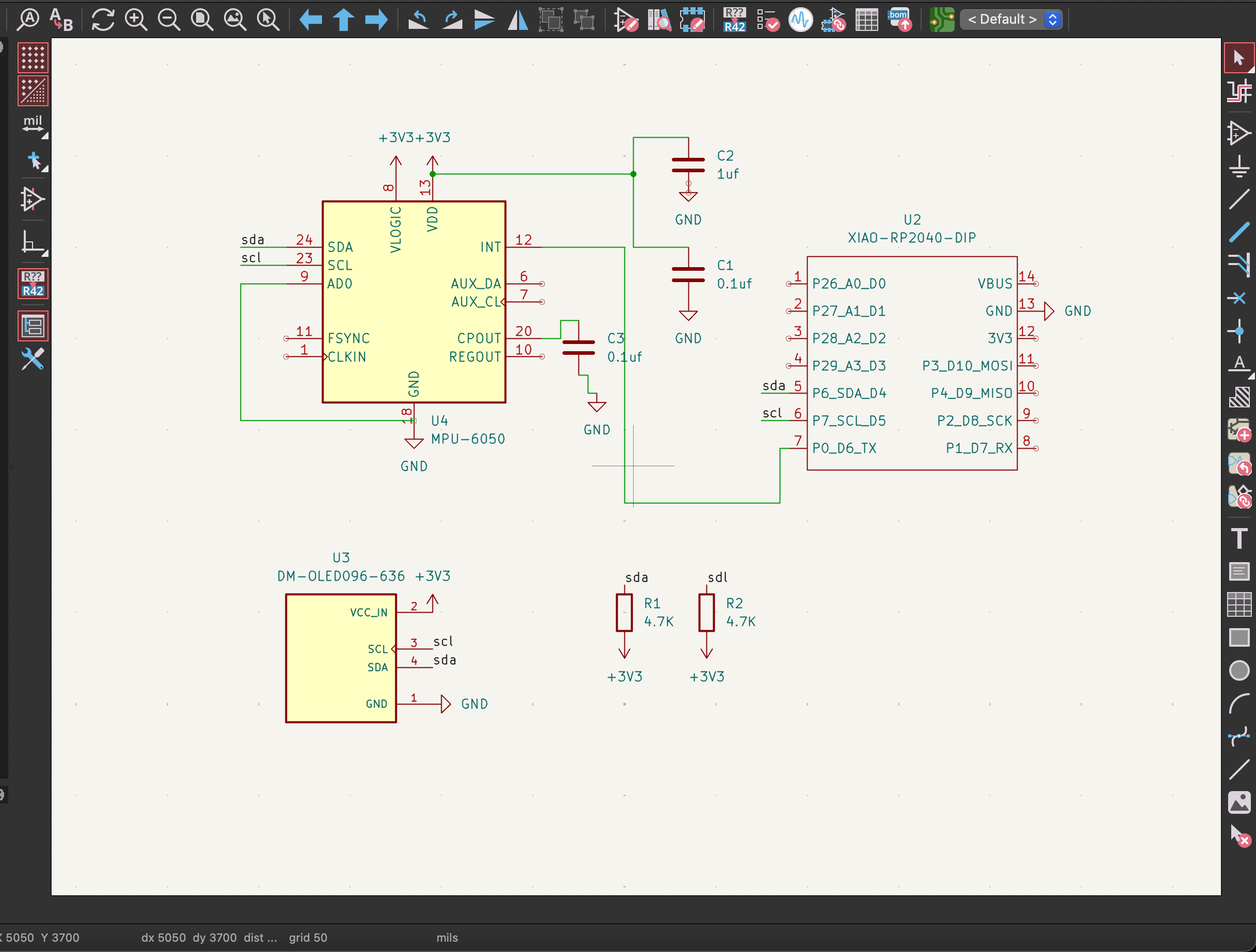
The board was created in KiCad.
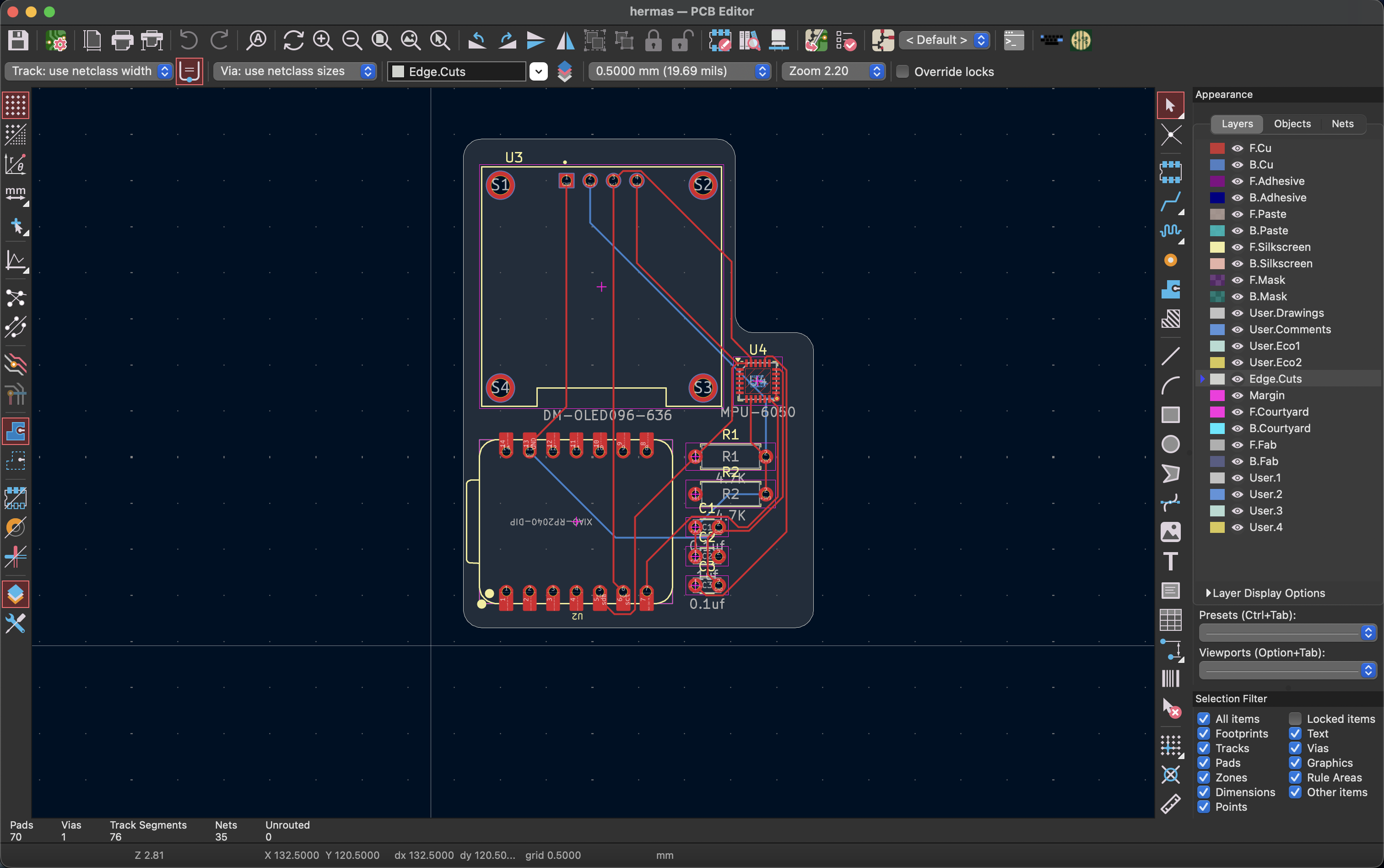
As MPU6050 is a tiny QFN device, I spent much time making sure that everything in the datasheet and footprint was checked properly. Routing the board was quite easy due to the fact that most of the connections were only four pins:
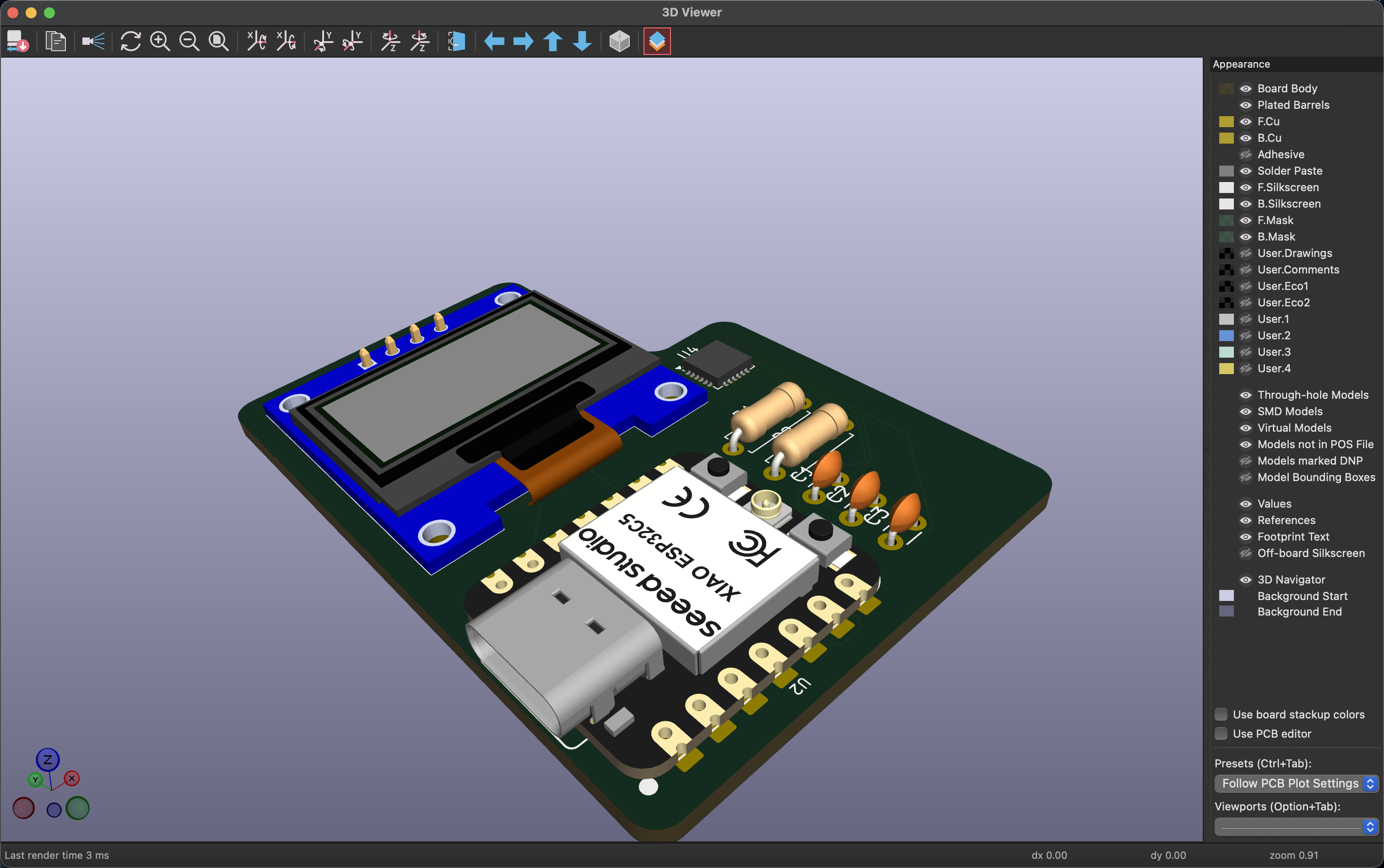
OLED and XIAO RP2040 are connected via headers, whereas MPU6050 and passives were soldered to the PCB.
Additionally, I have added silkscreen labels in order to simplify the assembly process.
| Part | Function | Quantity | Supplier |
|---|---|---|---|
| Seeed XIAO RP2040 | Main microcontroller for processing sensor data and controlling the display | 1 | Seeed Studio |
| MPU6050 | 3-axis accelerometer and 3-axis gyroscope sensor for motion detection | 1 | Robu.in |
| 0.96" OLED Display (SSD1306 I²C) | Displays real-time acceleration and rotation data | 1 | Robu.in |
| 4.7kΩ Resistor | I²C SDA pull-up resistor | 1 | Generic |
| 4.7kΩ Resistor | I²C SCL pull-up resistor | 1 | Generic |
| 0.1µF Capacitor | Decoupling capacitor for MPU6050 power stabilization | 2 | Generic |
| 1µF Capacitor | Power filtering capacitor | 1 | Generic |
| Custom PCB | Main circuit board for all components | 1 | LionCircuits |
| Component | Purchase Link |
|---|---|
| Seeed XIAO RP2040 | Seeed Studio Product Page |
| Seeed XIAO RP2040 (India) | Robu.in Product Page |
| MPU6050 Sensor Module | Robu.in MPU6050 Module |
| MPU6050 IC | Robu.in MPU6050 IC |
| 0.96" OLED Display (SSD1306 I²C) | Robu.in OLED Display (Blue) |
| 0.96" OLED Display (SSD1306 I²C) | Robu.in OLED Display (White) |
| 0.96" OLED Display (SSD1306 I²C) | Robu.in OLED Display (128×64 SSD1306) |
| 4.7kΩ Resistor | Robu.in Resistors Collection |
| 0.1µF Ceramic Capacitor | Robu.in Capacitors Collection |
| 1µF Capacitor | Robu.in Capacitors Collection |
| PCB Manufacturing | LionCircuits |
The Hermes Motion Meter is built around the Seeed XIAO RP2040 microcontroller. Motion sensing is provided by the MPU6050 IMU, which combines a 3-axis accelerometer and a 3-axis gyroscope. A 0.96-inch SSD1306 OLED display connected through the I²C bus is used to display sensor readings in real time.
The I²C communication lines (SDA and SCL) use 4.7kΩ pull-up resistors. Two 0.1µF decoupling capacitors and one 1µF filtering capacitor are included to ensure stable operation of the MPU6050 and reduce power supply noise. All components are mounted on a custom-designed PCB manufactured through LionCircuits.
Upon receiving the PCB and components, I proceeded to assemble the circuit.
The MPU6050 module was the hardest part due to its tiny size; I applied flux and soldered each pin making sure there were no solder bridges. After the MPU6050 module had been soldered, all other components were much easier to solder.
Then I soldered passive components, and after that the OLED header and the XIAO RP2040 headers.
After assembling the board, I flashed the firmware and tested whether the sensor was working using I²C.
Firmware is used to initialize MPU6050 and OLED via the I²C bus.
Display shows:
XIAO RP2040 is always reading data from MPU6050 and updating OLED display.
From this project, I learned about:
Overall, Hermes was an enjoyable project that provided a lot of valuable experience in developing a custom-made sensor board.
| Qty | Value | Footprint | References |
|---|---|---|---|
| 2 | 0.1uf | Capacitor_THT:C_Disc_D3.0mm_W1.6mm_P2.50mm | C1, C3 |
| 2 | 4.7K | Resistor_THT:R_Axial_DIN0207_L6.3mm_D2.5mm_P7.62mm_Horizontal | R1, R2 |
| 1 | 1uf | Capacitor_THT:C_Disc_D3.0mm_W1.6mm_P2.50mm | C2 |
| 1 | DM-OLED096-636 | DM-OLED096-636 (1):MODULE_DM-OLED096-636 | U3 |
| 1 | MPU-6050 | Sensor_Motion:InvenSense_QFN-24_4x4mm_P0.5mm | U4 |
| 1 | XIAO-RP2040-DIP | Seeed Studio XIAO Series Library:XIAO-RP2040-DIP | U2 |

ZhuYanzhen1/MM32_CLion
本项目是全国大学生智能车竞赛GDUT 2022年极速越野组的项目文件。采用了LQR控制器和多速率卡尔曼融合算法,并在单片机上实现。This project is the project document for the GDUT 2022 Extreme Off-Road Category of the National Student Intelligent Vehicle Competition.


victorhook/asac-fc
asac fc is an rp2040 based flight controller made for FPV drone flying


pms67/PModlet
PMOD PCB with USB-to-UART converter and IMU (MPU-6050, I2C) for FPGAs.
It measures 38 × 53 mm and has 2 copper layers, 1.6 mm thick.
8 parts, built around the MPU-6050. The full list of its parts is on this page, with links to each part's symbol and footprint where PCBKit's library has them.
From the AYUSH-pro-grammer/hermes repository on GitHub, at the commit this page was made from: the board is kicad/hermas.kicad_pcb and its schematic kicad/hermas.kicad_sch. PCBKit opens the board in the browser, with nothing to install.
Its repository states no licence, so its author keeps all rights: ask AYUSH-pro-grammer before reusing the design.