Skip to the content
4 layers147.2 × 96.3 mmShieldPCB, the printed circuit board in 3D

Hardware Design Files for Experimental Stimulation Platform (Gen 3)

Size
147.2 × 96.3 mm
Copper layers
4
Thickness
1.6 mm
Parts
142
Nets
136
Pads
583
Tracks, vias
1,232, 298
Pours
14
Routed
Yes
KiCad
KiCad 10.0 (file 20260206)
Created
13 Apr 2026
Updated
3 Oct 2026

Overview

ShieldPCB is an open-source printed circuit board by AErbsloeh, from the AErbsloeh/stimulation_genv3 repository on GitHub, published under the MIT licence. It is a 4-layer board of 147.2 × 96.3 mm with 142 parts on 136 nets, routed with 1,232 tracks and 298 vias.

It is built around the AD8421ARZ, ADA4610-2ARMZ and AD5754AREZ, with the ADP5071AREZ-R7, ADG1419BRMZ and ADR421ARMZ among its other parts. Its parts include 46 capacitors, 39 resistors, 22 ICs, 11 connectors and 4 switches.

Main components

7

README

README.md

Design Files for an Experimental Stimulation Platform (Gen3)

This repo includes the KiCAD hardware files, the necessary firmware (C) and measurement scripts to use this stimulation platform.

Table of Content

  1. Concept
  2. Parameter Range
  3. Hardware Design
  4. Using the firmware
  5. Actual state

Concept

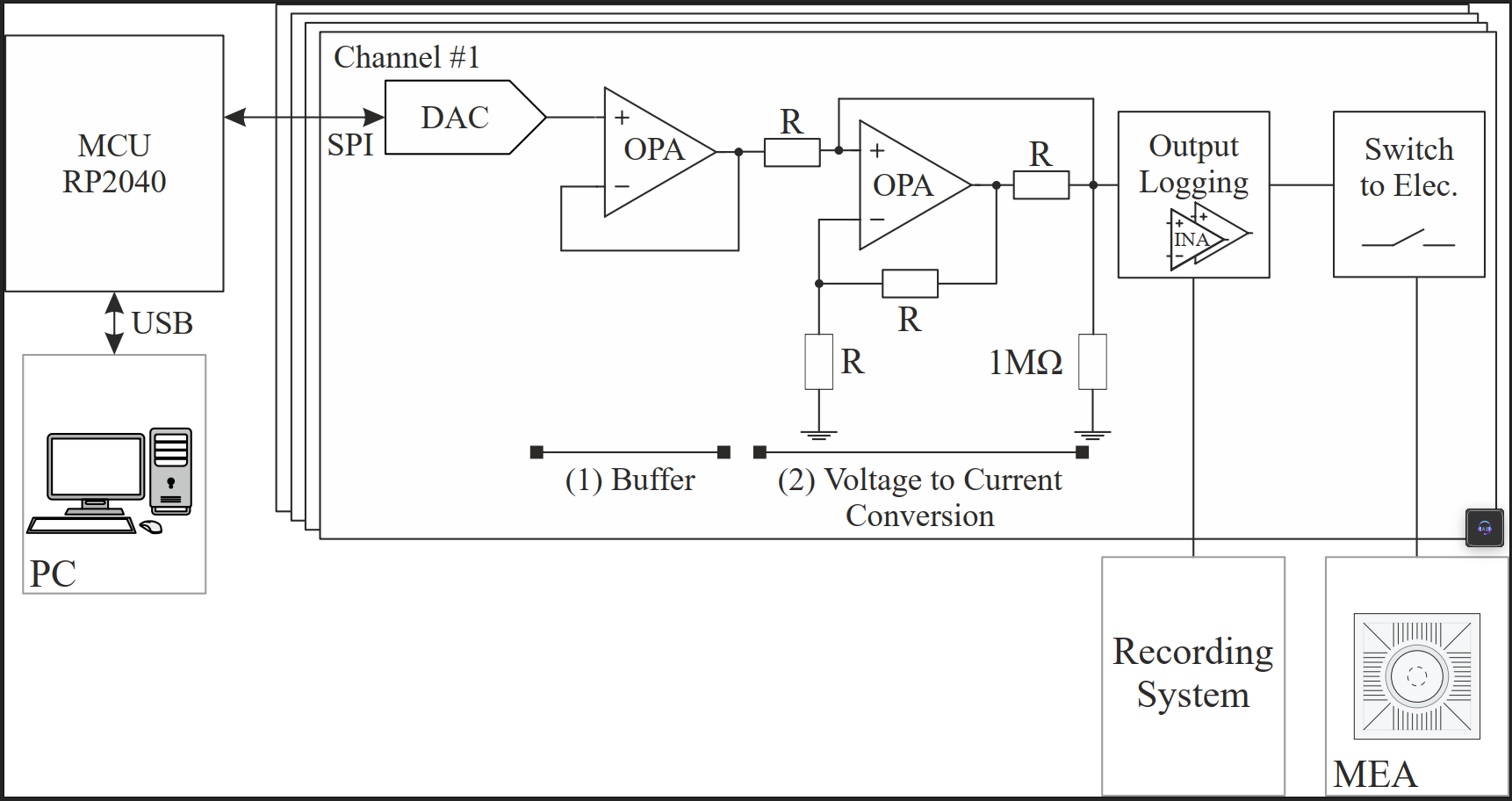
Beschreibung

Parameter Range

Output range +-200µA with +-15V voltage supply (either directy or using additional 5V USB-C supply). Using waveform generation on MCU (Pi Pico) time resolution around 2.5µs practical limit.

Hardware Design

See 1_kicad directory for schematics and PCB layout. See BOM for an interactive bill of materials.

Using the firmware

Recommened IDE: VS code combined with the Raspberry Pi Pico extension. Create a new C/C++ Project with the extension using the existing firmware_stimPlat_v3.c file from 2_firmware directory. Adapt the firmware_stimPlat_v3.c for your needed stimulation protocol and click on "Run Project (USB)" with connected platform in order to start the protocol. Outputs and debugging of the platform can be done using the Serial Monitor.

Alternatively, static characterization can be done using MicroPython control code on Pico and commuicationg via UART from computer using another python script. See directory 3_static_characterization_control. In general if speed is not an issue, e.g. low frequency rectangular waveforms, MicroPython control is an easy to use alternative.

Actual state

There will be no further improvements. There is still the development of the stimulation platform (Gen4).

Restrictions

  • While theoretical temporal limit is lower MCU here limits the possible realized frequencies. Frequencies of sine waves is modulated by number of LUT values for waveform generation. Calibration of used LUT length and resulting wavelet frequecy is recommended. Instead fixed LUT length and timer can be used (already implemented in Firmware) but restricts the realizable frequencies more because temporal resolution gets worse (because of timer overhead). Found temporal limit of around 10µs with enabled timer.
  • Hardware natively supports alternative FPGA control over PMOD connector

Further information

Further design and characterization information can be found in our paper.

Parts

142
QtyValueFootprintReferences
360.1uFCapacitor_SMD:C_0805_2012Metric_Pad1.18x1.45mm_HandSolderC1, C2, C3, C10, C11, C12, C13, C14, C15, C16, C17, C18, C19, C28, C29, C30 +20
810RResistor_SMD:R_0805_2012Metric_Pad1.20x1.40mm_HandSolderR7, R14, R28, R35, R40, R41, R42, R43
825kRResistor_SMD:R_0805_2012Metric_Pad1.20x1.40mm_HandSolderR3, R4, R10, R11, R24, R25, R31, R32
8AD8421AAD8421:RM_8_ADI-MIC1, IC2, IC4, IC5, IC7, IC8, IC10, IC11
8BNC-MALE-HConnectors_ShieldPCB:TE_1-1337445-0Elec1, Elec2, Elec3, Elec4, I_Elec_Log1, Stim_EN1, Stim_Status1, V_Elec_Log1
610uFCapacitor_SMD:C_0805_2012Metric_Pad1.18x1.45mm_HandSolderC44, C45, C47, C50, C52, C56
510kResistor_SMD:R_0805_2012Metric_Pad1.20x1.40mm_HandSolderR6, R13, R27, R34, R36
41000MRResistor_SMD:R_0805_2012Metric_Pad1.20x1.40mm_HandSolderR1, R8, R22, R29
410MegResistor_SMD:R_0805_2012Metric_Pad1.20x1.40mm_HandSolderR5, R12, R26, R33
4ADA4610-2ARMZConnectors_ShieldPCB:RM-8_ADI-LU3, U4, U7, U8
4ADG1419BRMZConnectors_ShieldPCB:SOP65P490X110-8NIC3, IC6, IC9, IC12
4MORNTA2502AT5Connectors_ShieldPCB:MORNTA2502AT5RN1, RN2, RN3, RN4
3Conn_ElecOut_ElecRefConnector_PinHeader_2.54mm:PinHeader_2x04_P2.54mm_VerticalJ7, J9, J12
20RResistor_SMD:R_0805_2012Metric_Pad1.20x1.40mm_HandSolderR2, R15
21uFCapacitor_SMD:C_0805_2012Metric_Pad1.18x1.45mm_HandSolderC53, C54
247nFCapacitor_SMD:C_0805_2012Metric_Pad1.18x1.45mm_HandSolderC51, C57
25k1Resistor_SMD:R_0805_2012Metric_Pad1.20x1.40mm_HandSolderR37, R38
2DFSL240Diode_SMD:D_PowerDI-123U11, U12
2SW_Rotary_1x4_MPConnectors_ShieldPCB:SWITCH_RM104772BCBSW2, SW3
1118kRResistor_SMD:R_0805_2012Metric_Pad1.20x1.40mm_HandSolderR39
112kRResistor_SMD:R_0805_2012Metric_Pad1.20x1.40mm_HandSolderR47
1137kRResistor_SMD:R_0805_2012Metric_Pad1.20x1.40mm_HandSolderR30
12M32RResistor_SMD:R_0805_2012Metric_Pad1.20x1.40mm_HandSolderR48
12M43RResistor_SMD:R_0805_2012Metric_Pad1.20x1.40mm_HandSolderR9
13.3uHConnectors_ShieldPCB:XAL40XXL1
15k6RResistor_SMD:R_0805_2012Metric_Pad1.20x1.40mm_HandSolderR23
16.8uHConnectors_ShieldPCB:WE-MAPI_4030_74438357068L2
1AD5754AREZDAC_AD5754:RE_24_ADIU2
1ADP5071AREZ-R7Connectors_ShieldPCB:RE-20-1_ADI-L_ADP5071U1
1ADR421ARMZPackage_SO:MSOP-8_3x3mm_P0.65mmU9
1Alt_AGND_BananaConnector:Banana_Cliff_FCR7350B_S16N-PC_HorizontalJ5
1Alt_SupplyConnector_PinHeader_2.54mm:PinHeader_1x03_P2.54mm_VerticalJ2
1Alt_VDD_BananaConnector:Banana_Cliff_FCR7350B_S16N-PC_HorizontalJ4
1Alt_VSS_BananaConnector:Banana_Cliff_FCR7350B_S16N-PC_HorizontalJ6
1Conn_02x02_Odd_EvenConnector_PinHeader_2.54mm:PinHeader_2x02_P2.54mm_VerticalJ10
1Conn_02x08_Odd_EvenConnector_PinHeader_2.54mm:PinHeader_2x08_P2.54mm_VerticalJ8
1Conn_02x13_Counter_ClockwiseConnectors_ShieldPCB:FAKE_PICO_ConnectJ1
1PMODConnector_PinHeader_2.54mm:PinHeader_2x06_P2.54mm_HorizontalU10
1SW_DIP_x06Connectors_ShieldPCB:418127160906SW5
1USB4125-GF-A_REVA2Connectors_ShieldPCB:GCT_USB4125-GF-A_REVA2J3
1~Connectors_ShieldPCB:ANT33FAR2S25RESW4

The 136 most common of 142 parts.

Similar boards

  • 2 layers104 × 121 mmNAVMATE Testopstelling, the printed circuit board in 3D

    NAVMATE Testopstelling

    mitaadevelop/NAVMATE-Testopstelling

    Firmware (NXP LPC1752, C) + PC-gereedschap (Python) voor een maritiem navigatie-testinstrument. De MCU leest scheepssensoren via een 24-bit ADC, stuurt drie analoge uitgangen aan via DAC's en streamt op commando van de…

    154 parts
  • 6 layers54 × 29 mmADC7177M1, the printed circuit board in 3D

    ADC7177M1

    BehrensG/ADC7177M1

    ADC module based on AD7177-2.

    133 parts
  • 2 layers106.7 × 78.4 mmADC, the printed circuit board in 3D

    ADC

    Dinh-Dai/ADC-converter

    199 parts
  • 2 layers69.5 × 47 mmBackupECG2, the printed circuit board in 3D

    BackupECG2

    namtu06/ecg-amplifier

    Designing an ECG amplifier from scratch with KiCad (part of Biomedical Instrumentation coursework)

    30 parts
  • 2 layersArdupotentio, the printed circuit board in 3D

    Ardupotentio

    woongzeyi/project_archive

    Bunch of un-git-ted finished projects that are archived "properly".

    43 parts
  • 2 layers100 × 100 mmAmplifier, the printed circuit board in 3D

    Amplifier

    PatrickJohnDavies/Hydrophone

    107 parts8
  • 2 layers86 × 71 mmCurrent voltage input, the printed circuit board in 3D

    Current voltage input

    RWTH-ACS/current-voltage-input

    Input Stage for three phase voltage and current in the low voltage grid

    153 parts2CERN-OHL-W-2.0
  • 6 layers100.7 × 106.4 mmSignal processing unit, the printed circuit board in 3D

    Signal processing unit

    scalinq-lab/cryomagsens

    The sensor unit was designed in KiCad 10 and manufactured by JLCPCB. It is built in a flex PCB material to achieve a very small build height, in order to come very close to the device under test.

    178 parts2CERN-OHL-P-2.0

Questions

How big is the ShieldPCB PCB?

It measures 147.2 × 96.3 mm and has 4 copper layers, 1.6 mm thick.

What parts does the ShieldPCB use?

142 parts, built around the AD8421ARZ, ADA4610-2ARMZ, AD5754AREZ and ADP5071AREZ-R7. The full list of its parts is on this page, with links to each part's symbol and footprint where PCBKit's library has them.

Where can I download the ShieldPCB KiCad files?

From the AErbsloeh/stimulation_genv3 repository on GitHub, at the commit this page was made from: the board is 1_kicad/ShieldPCB.kicad_pcb and its schematic 1_kicad/Channel.kicad_sch. PCBKit opens the board in the browser, with nothing to install.

Can I use the ShieldPCB design in my own project?

Its repository publishes it under the MIT licence: you may reuse it on that licence's terms (keep the author's notice, and for a copyleft licence share your changes alike).