2 layers52 × 50 mm

 74th/ch32v-dev-boards11
Rvswdio programmer is an open-source printed circuit board by 74th, from the 74th/ch32v-dev-boards repository on GitHub, published under the MIT licence. It is a 2-layer board of 15.5 × 36.6 mm with 21 parts on 30 nets, routed with 129 tracks and 39 vias.
It is built around the CH32V003F4P6, AMS1117 and CH217K. Its parts include 10 resistors, 5 capacitors, 3 ICs and 1 connector. It belongs with the interfaces and adapters boards and the RISC-V boards of this library.


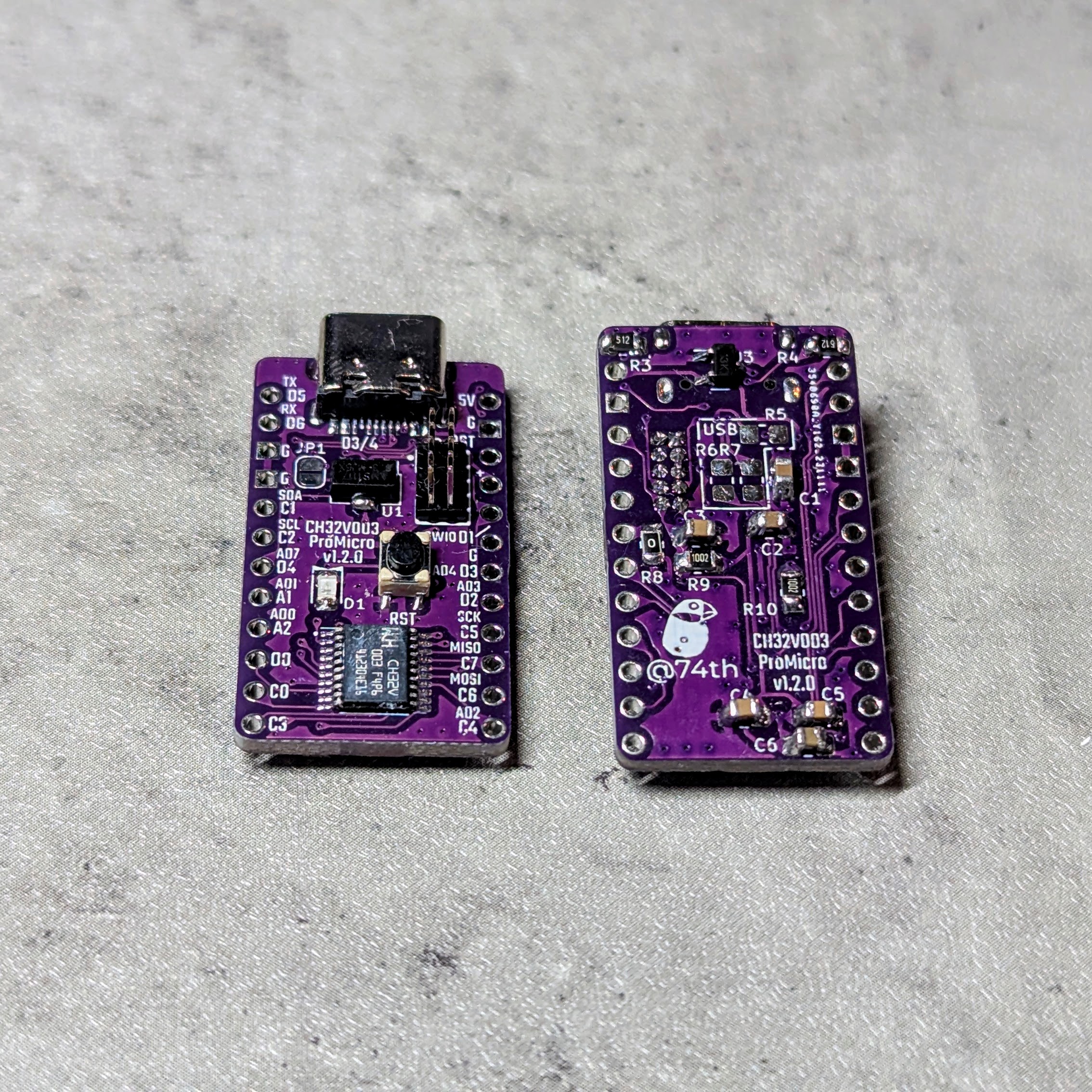
Shop(Booth, Japan): https://booth.pm/ja/items/4645948
🇯🇵
🇯🇵
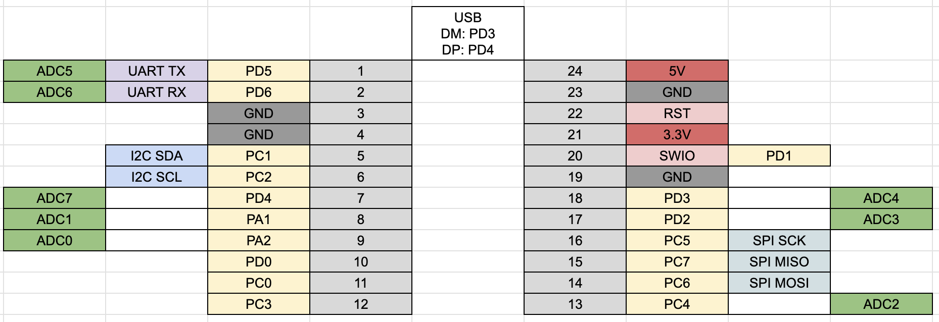
| Reference | Name | Quantity |
|---|---|---|
| C1, C2 | Capacitor 0805 10uF | 2 |
| C3-C5 | Capacitor 0805 100nF | 3 |
| C6 | Capacitor 0805 1uF | 1 |
| D1 | LED 0805 Blue | 1 |
| J1 | USB Type-C Receptacle | 1 |
| J2 | Pin Header 2x5 Pitch 1.27mm | 1 |
| JP1 | Jumper SolderJumper_2_Open | 1 |
| R3, R4 | Register 0805 5.1kΩ | 2 |
| R5 | Register 0805 1.5kΩ (NC) | 1 |
| R6, R7 | Register 0805 27.4Ω (NC) | 2 |
| R8 | Register 0805 0Ω | 1 |
| R9, R10 | Register 0805 10kΩ | 2 |
| SW1 | Button SKRPABE010 | 1 |
| U1 | Regulator 3.3V SOT-89 AMS1117-3.3 | 1 |
| U2 | MCU TSSOP20 WCH CH32V003F4P6 | 1 |
🇯🇵
| Reference | Name | Quantity |
|---|---|---|
| C1, C2 | Capacitor 0805 10uF | 2 |
| C3-C5 | Capacitor 0805 100nF | 3 |
| C6 | Capacitor 0805 1uF | 1 |
| D1 | LED 0805 Blue | 1 |
| J1 | USB Type-C Receptacle - USB2.0_C_v3 | 1 |
| J2 | Box Pin Header 2x5 Pitch 1.27mm | 1 |
| JP1 | Jumper SolderJumper_2_Open | 1 |
| R1, R9, R10 | Register 0805 10kΩ | 3 |
| R2 | Register 0805 54-56kΩ | 1 |
| R3, R4 | Register 0805 5.1kΩ | 2 |
| R5 | Register 0805 1.5kΩ (NC) | 1 |
| R6, R7 | Register 0805 27.4Ω (NC) | 2 |
| R8 | Register 0805 0Ω | 1 |
| SW1 | Button SKRPABE010 | 1 |
| U1 | Regulator 3.3V SOT-89 AMS1117-3.3 | 1 |
| U2 | MCU TSSOP20 WCH CH32V003F4P6 | 1 |
| U3 | USB Power Protection IC SOT-23-6L CH217K | 1 |
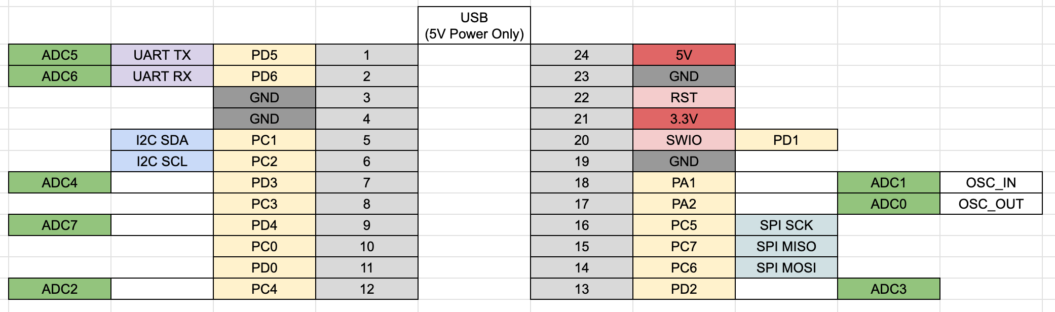
| Reference | Parts |
|---|---|
| R1 | 0805 Register 10k |
| R2,R3 | 0805 Register 5.1kR |
| R4 | 0805 Register 200R or 1kR |
| R5 | 0805 Register 0R |
| C1,C2,C3 | 0805 Capacitor 100nF |
| C4,C5 | 0805 Capacitor 22p (NC) |
| C6 | 0805 Capacitor 10uF |
| C7 | 0805 Capacitor 2.2uF |
| D1 | 0805 LED |
| U1 | TSSOP20 CH32V003F4P6 |
| U2 | SOT89 3.3V Regulator AMS1117-3.3 |
| Y1 | 3225 4Pin Crystal 24MHz (NC) |
| J1 | SMD USB-C 2.0 Socket |
| SW1 | SKRPABE010 SMD Push Switch |
| Qty | Value | Footprint | References |
|---|---|---|---|
| 5 | 10 | 74th:Register_0603_1608 | R4, R5, R6, R7, R8 |
| 3 | 5.1k | 74th:Register_0603_1608 | R1, R2, R9 |
| 2 | 10u | 74th:Capacitor_0603_1608 | C3, C4 |
| 2 | 1u | 74th:Capacitor_0603_1608 | C2, C5 |
| 1 | 1.5k | 74th:Register_0603_1608 | R3 |
| 1 | 100n | 74th:Capacitor_0603_1608 | C1 |
| 1 | 22k | 74th:Register_0603_1608 | R10 |
| 1 | AMS1117 | 74th:Package_SOT-89-3 | U2 |
| 1 | CH217K | 74th:Package_SOT-23-6 | U3 |
| 1 | CH32V003F4P6 | 74th:Package_TSSOP-20_4.4x6.5mm_P0.65mm | U1 |
| 1 | Pin_6 | 74th:PinOut_Pin_6_GND | CH2 |
| 1 | SWD | 74th:PinOut_Pin_3_3GND | CH1 |
| 1 | USB2.0-C_SMT | 74th:Connector_USB-C-Receptacle_SMT_12-Pin_Simple | J1 |


arkadiuszmakarenko/RISKYMSX
RISKY MSX Cartridge based on WCH CH32V303V chip. It is 256KB cart programmed using USB Fat32 flash drive

openwch/ch334
Share the schematic and layout (KiCad) for DIY USB2.0 4-PORTS HUB with CH334U

AnterCreeper/pdaltmode
USB Power Delivery Alt-mode Negotiation using CH32X035


74th/esp32c3-iot-server-board
Board for converting Grove device to IoT Server using ESP32-C3-WROOM-02.
It measures 15.5 × 36.6 mm and has 2 copper layers, 1.6 mm thick.
21 parts, built around the CH32V003F4P6, AMS1117 and CH217K. The full list of its parts is on this page, with links to each part's symbol and footprint where PCBKit's library has them.
From the 74th/ch32v-dev-boards repository on GitHub, at the commit this page was made from: the board is rvswdio-programmer/rvswdio-programmer.kicad_pcb and its schematic ch32v003-promicro/ch32v003-promicro.kicad_sch. PCBKit opens the board in the browser, with nothing to install.
Its repository publishes it under the MIT licence: you may reuse it on that licence's terms (keep the author's notice, and for a copyleft licence share your changes alike).