2 layers119.4 × 76.2 mm

 5a7man/PCBs
A random collection of designed PCBs
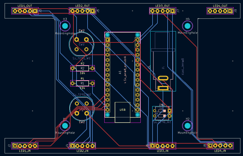
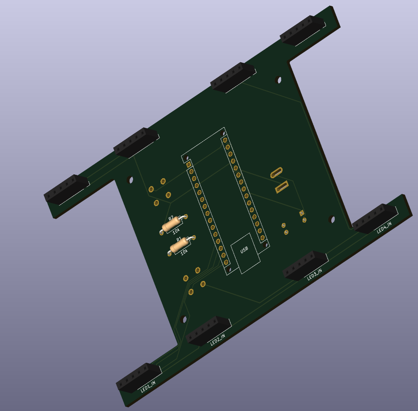
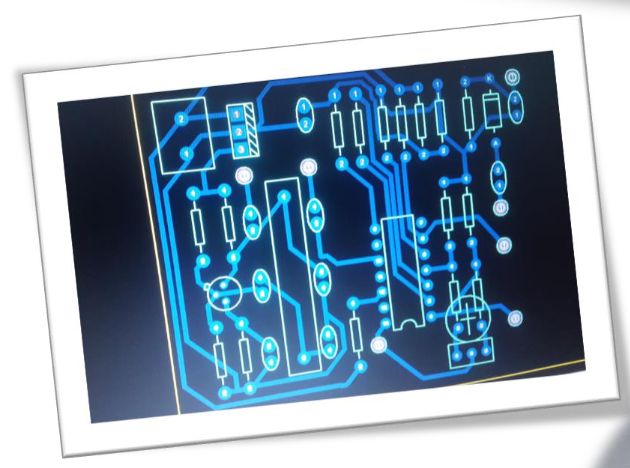
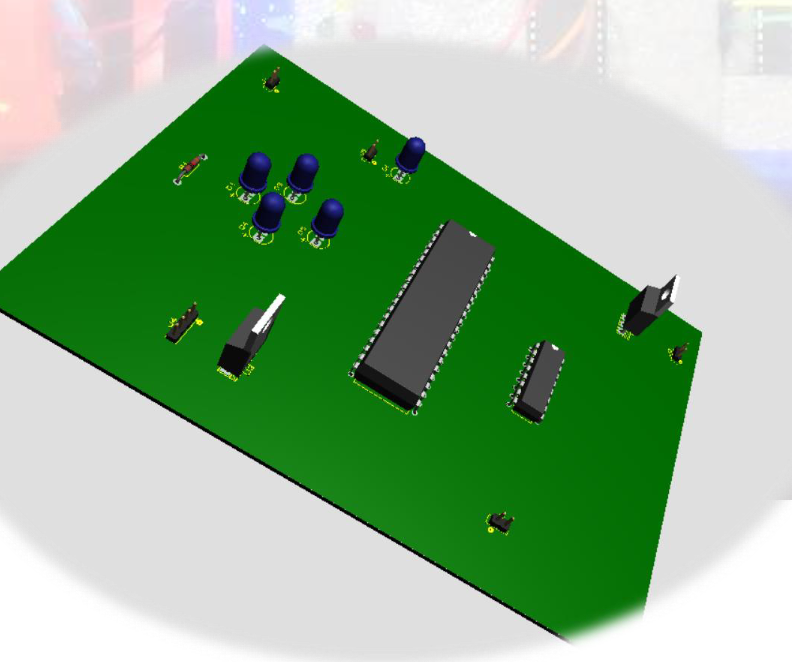
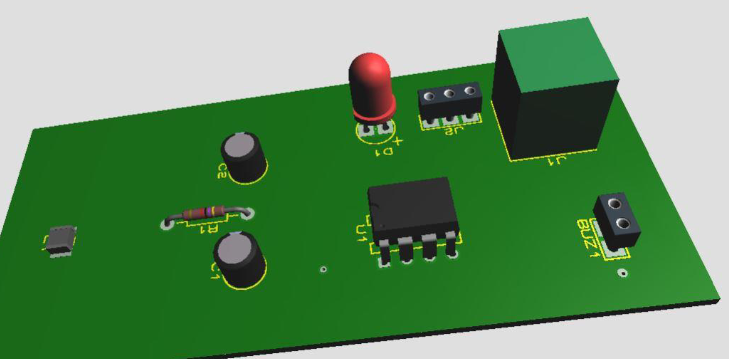
AVR Datalogger is an open-source printed circuit board by 5a7man, from the 5a7man/PCBs repository on GitHub. It is a 4-layer board of 48.5 × 43.4 mm with 29 parts on 34 nets, routed with 331 tracks and 22 vias.
It is built around the ATMEGA328P-AU and DS1337S+T&R. Its parts include 7 resistors, 5 capacitors, 4 ICs, 4 connectors and 2 diodes. It belongs with the sensors and measurement boards and the AVR (ATmega, ATtiny) boards of this library.


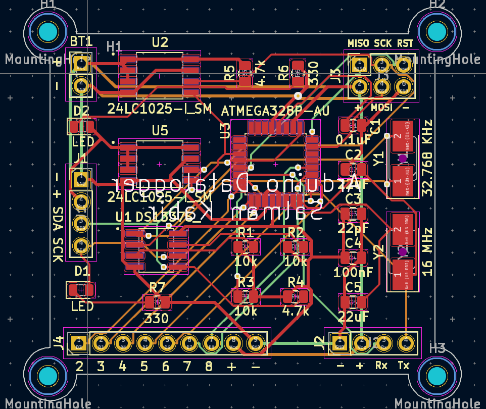
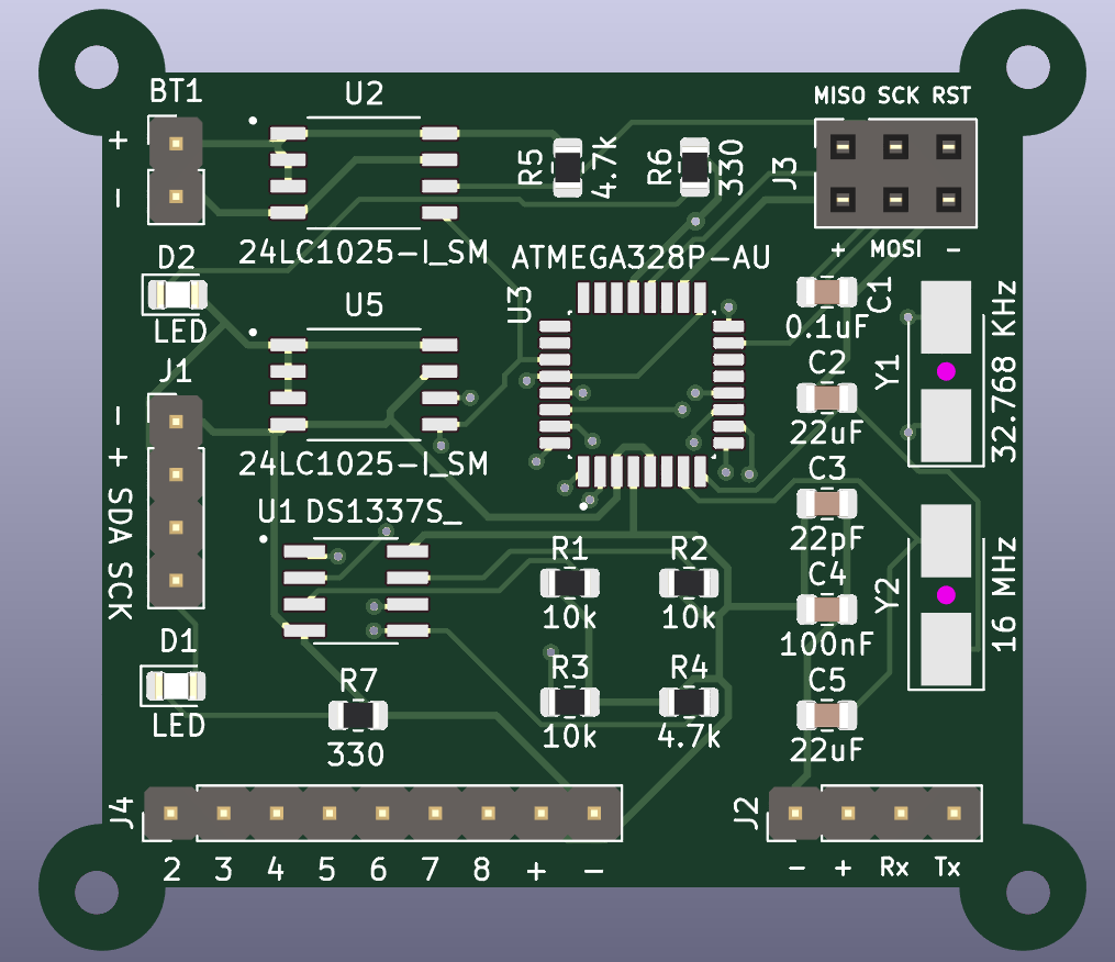
| Qty | Value | Footprint | References |
|---|---|---|---|
| 4 | MountingHole | MountingHole:MountingHole_2.1mm | H1, H2, H3, H4 |
| 3 | 10k | Resistor_SMD:R_0805_2012Metric | R1, R2, R3 |
| 2 | 22uF | Capacitor_SMD:C_0805_2012Metric | C2, C5 |
| 2 | 24LC1025-I_SM | 24LC1025-I_SM:SOIC127P794X202-8N | U2, U5 |
| 2 | 330 | Resistor_SMD:R_0805_2012Metric | R6, R7 |
| 2 | 4.7k | Resistor_SMD:R_0805_2012Metric | R4, R5 |
| 2 | Conn_01x04_Pin | Connector_PinHeader_2.54mm:PinHeader_1x04_P2.54mm_Vertical | J1, J2 |
| 2 | LED | LED_SMD:LED_0805_2012Metric | D1, D2 |
| 1 | 0.1uF | Capacitor_SMD:C_0805_2012Metric | C1 |
| 1 | 100nF | Capacitor_SMD:C_0805_2012Metric | C4 |
| 1 | 16 MHz | Crystal:Crystal_SMD_5032-2Pin_5.0x3.2mm_HandSoldering | Y2 |
| 1 | 22pF | Capacitor_SMD:C_0805_2012Metric | C3 |
| 1 | 32.768 KHz | Crystal:Crystal_SMD_5032-2Pin_5.0x3.2mm_HandSoldering | Y1 |
| 1 | ATMEGA328P-AU | ATMEGA328P-AU:QFP80P900X900X120-32N | U3 |
| 1 | Battery | Connector_PinHeader_2.54mm:PinHeader_1x02_P2.54mm_Vertical | BT1 |
| 1 | Conn_01x09_Pin | Connector_PinHeader_2.54mm:PinHeader_1x09_P2.54mm_Vertical | J4 |
| 1 | Conn_02x03_Odd_Even | Connector_PinSocket_2.54mm:PinSocket_2x03_P2.54mm_Vertical | J3 |
| 1 | DS1337S_ | DS1337S_:SOIC127P600X175-8N | U1 |


futureshocked/KLP4e_MCU-Datalogger
This is the repository for the "MCU Datalogger" project.

futureshocked/KicadLikeAPro-Project-3-BACEE
This is one of the PCB projects from the Kicad Like a Pro book. It contains a two and four layer board that implements an Arduino clone with external EEPROM and a clock.

DevMajed/DataLogger-Board
Hardware PCB Design for AVR-based Datalogger using KiCAD


GildardoRestrepo/course_electronics_design
Repositorio de actividades entregables del curso de diseño electrónico. UPB 2026-02

lologog/MCU_DataLogger
A microcontroller-based device for logging and storing data from external sensors. The data is saved to EEPROM memory for later retrieval and analysis

It measures 48.5 × 43.4 mm and has 4 copper layers, 1.6 mm thick.
29 parts, built around the ATMEGA328P-AU and DS1337S+T&R. The full list of its parts is on this page, with links to each part's symbol and footprint where PCBKit's library has them.
From the 5a7man/PCBs repository on GitHub, at the commit this page was made from: the board is AVR_Datalogger/AVR_Datalogger.kicad_pcb and its schematic AVR_Datalogger/AVR_Datalogger.kicad_sch. PCBKit opens the board in the browser, with nothing to install.
Its repository states no licence, so its author keeps all rights: ask 5a7man before reusing the design.