2 layers50.2 × 31.2 mm
MCU Datalogger
futureshocked/KLP4e_MCU-Datalogger
This is the repository for the "MCU Datalogger" project.
31 parts138MIT

 lologog/MCU_DataLogger1
A microcontroller-based device for logging and storing data from external sensors. The data is saved to EEPROM memory for later retrieval and analysis
MCU DataLoggerPCB is an open-source printed circuit board by lologog, from the lologog/MCU_DataLogger repository on GitHub, published under the MIT licence. It is a 2-layer board of 52.2 × 34.4 mm with 30 parts on 35 nets, routed with 271 tracks and 54 vias.
It is built around the ATMEGA328P-AU, 24LC1025-I/P and DS1337S+T&R. Its parts include 7 resistors, 5 capacitors, 4 ICs, 4 connectors and 2 diodes. It belongs with the sensors and measurement boards and the AVR (ATmega, ATtiny) boards of this library.


In many embedded systems, there is often a lack of non-volatile or a dedicated mechanism for long-term data logging. Sensor readings, digital signals or communication data are frequently lost or must be transmitted in real time, which can be inconvenient or require constant infrastructure.
To address this limitation, I developed a compact data logger that acts as an independent module capable of storing data for later analysis. The device can capture data from digital or receive custom data frames sent by other devices via a communication bus.
The hardware is build around an ATmega328p microcontroller running with an external 16MHz crystal oscillator, ensuring stable and precise timing for all operations. Data may be stored in two external 24LC1025 I2C EEPROM chips, which provide a large amount of non-volatile memory for long-term data logging. An additional DS1337S+ RTC module keeps accurate time for timestamping logged events.
The board includes two LEDs: one serves as a power indicator, while the second is user-programmable and can be freely controlled by the firmware for signaling various system states. External connection are provided for 5 V power input, six digital inputs and accompanying +5 V and GND rails for convenient sensor or signal wiring. Communication and programming interfaces are also available through UART, I2C and SPI/ICSP headers.
The PCB has been designed with mechanical integration in mind. It can be easily mounted inside the custom 3D-printed enclosure, with precisely aligned M2 mounting holes and standoff positions that provide a secure fit between the base and the upper part of the case.
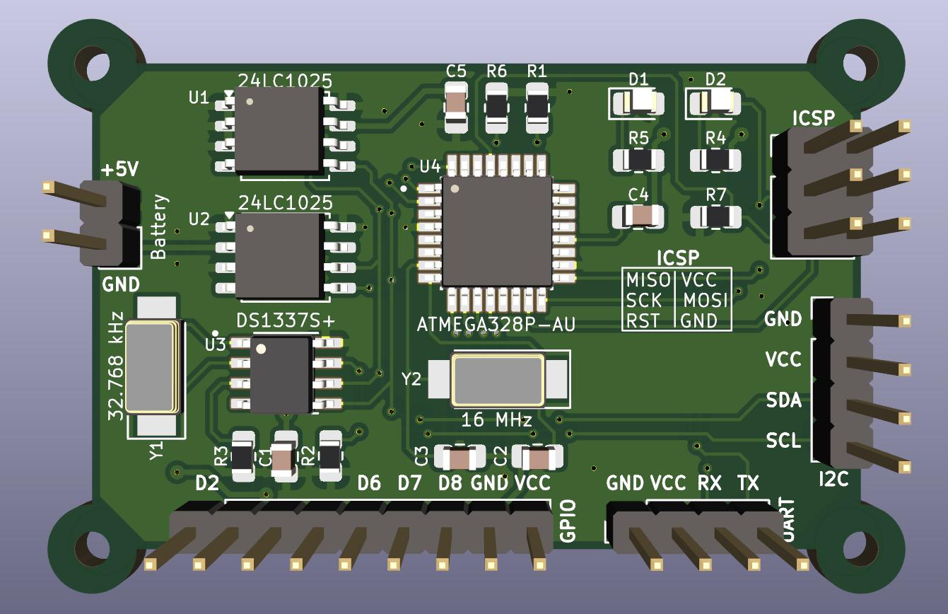 3D render of the PCB board made in KiCad software
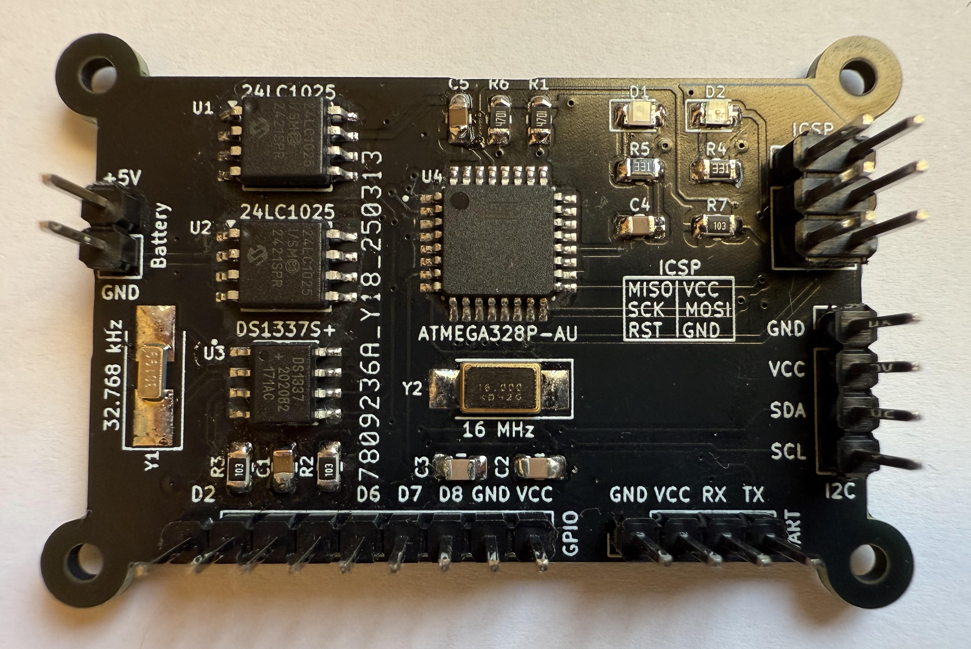 Finished PCB board
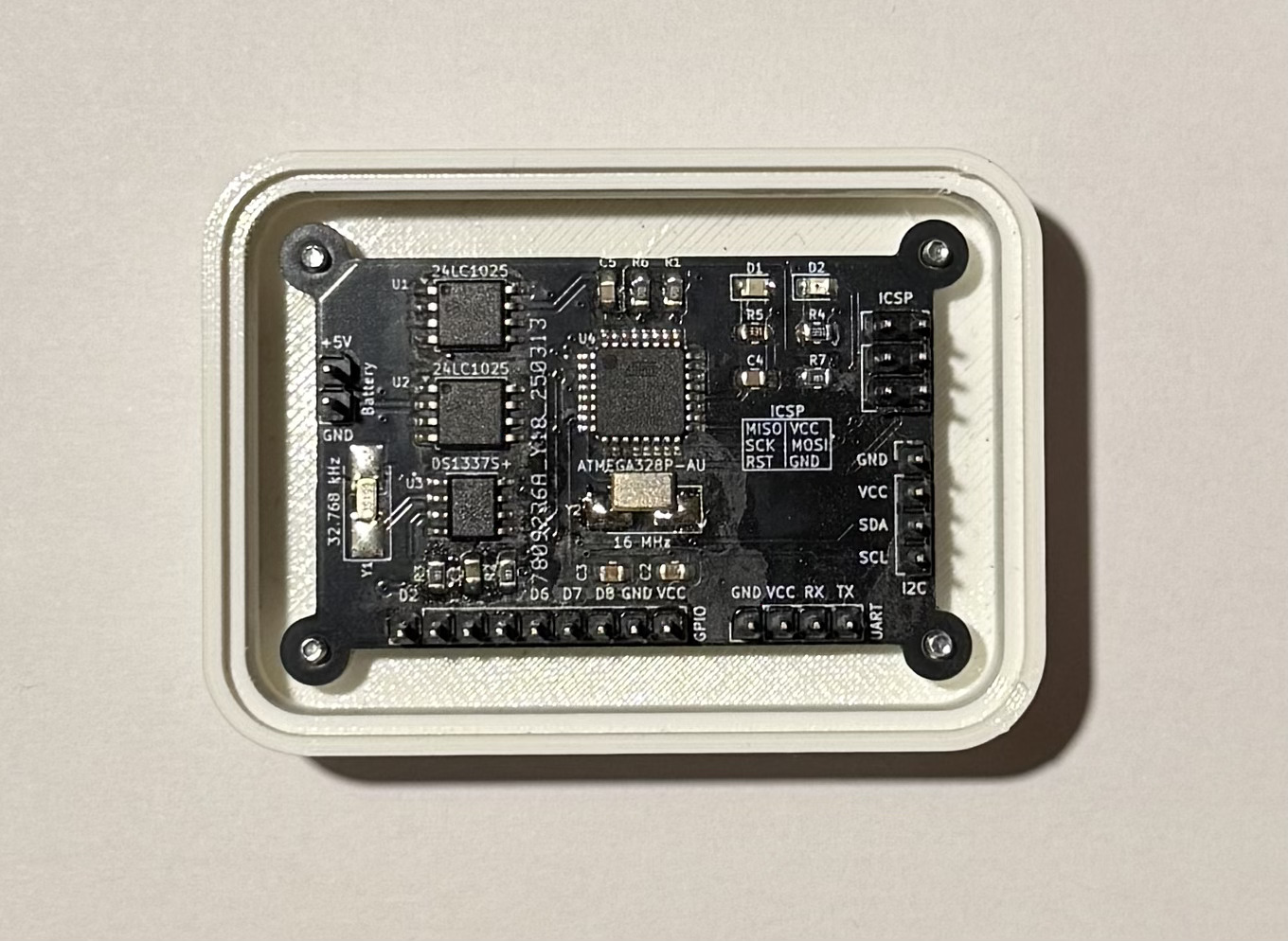 PCB board with bottom part of the enclosure
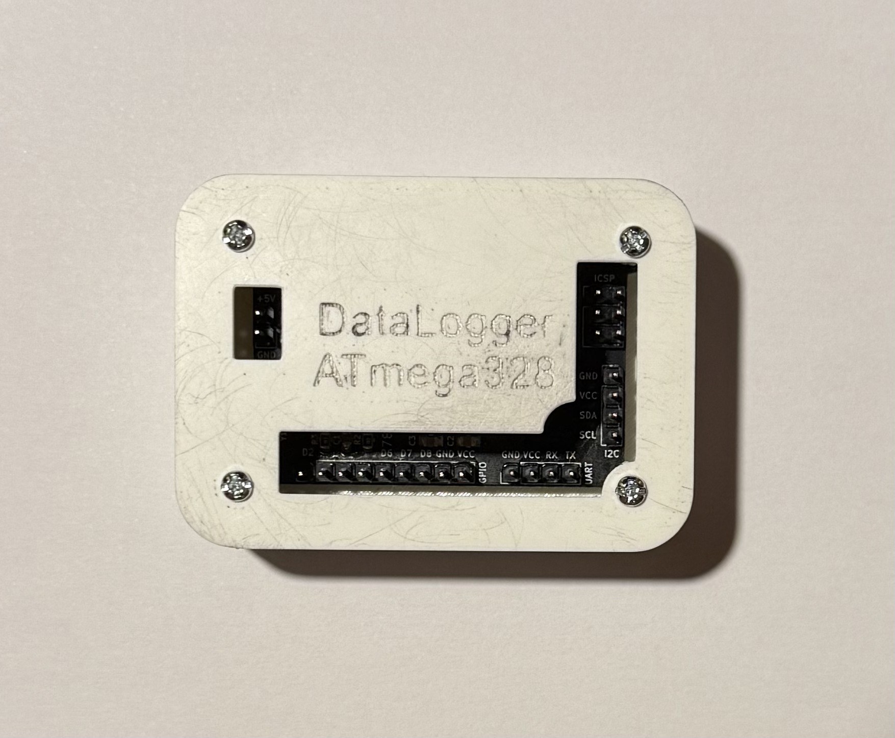 Assembled device
To demonstrate the flexibility of the MCU Data Logger platform, a sample firmware project project was implemented for monitoring office windows.
The system uses six magnetic reed switches (contact sensors) connected to the digital inputs of the board. It continuously monitors each window's state, counts the number of openings and calculates the total time each window remains open.
The device communicates with a PC via UART, accepting three command codes:
This allows the user to easily monitor and control the logger from a serial console or custom PC software.
The firmware was written entirely in C and designed to be modular, reusable and easy to extend for different data-logging applications. It is divided into two layers: a set of core low-level drivers and an application layer implementing the example project logic.
These modules provide essential hardware functionality and can be reused across multiple projects built on this platform:
This section implements the Office Window Monitor example, showcasing how the data logger can be adapted to real-world tasks:
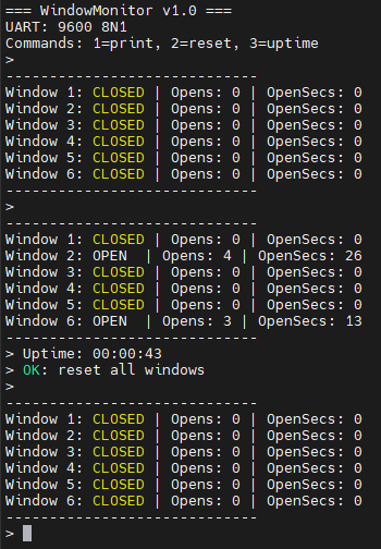
After startup, the device displays basic information such as firmware version, UART settings and available commands. The first readout shows the initial state where all windows are closed. After a short time, another read reveals that window 2 and 6 have been opened several times, with their total open duration displayed. Next, the system uptime is requested and shown as 00:00:43. Finally, the reset command is issued, clearing all stored data - the last read confirms that all counters and timers have returned to zero.
| Qty | Value | Footprint | References |
|---|---|---|---|
| 4 | MountingHole | MountingHole:MountingHole_2.2mm_M2 | H1, H2, H3, H4 |
| 3 | 10k | Resistor_SMD:R_0805_2012Metric_Pad1.20x1.40mm_HandSolder | R2, R3, R7 |
| 2 | 0.1uF | Capacitor_SMD:C_0805_2012Metric_Pad1.18x1.45mm_HandSolder | C1, C4 |
| 2 | 22pF | Capacitor_SMD:C_0805_2012Metric_Pad1.18x1.45mm_HandSolder | C2, C3 |
| 2 | 24LC1025 | Package_SO:SOIC-8_5.3x5.3mm_P1.27mm | U1, U2 |
| 2 | 330 | Resistor_SMD:R_0805_2012Metric_Pad1.20x1.40mm_HandSolder | R4, R5 |
| 2 | 4.7k | Resistor_SMD:R_0805_2012Metric_Pad1.20x1.40mm_HandSolder | R1, R6 |
| 2 | Conn_01x04_Pin | Connector_PinHeader_2.54mm:PinHeader_1x04_P2.54mm_Vertical | J1, J2 |
| 2 | LED | LED_SMD:LED_0805_2012Metric_Pad1.15x1.40mm_HandSolder | D1, D2 |
| 1 | 100nF | Capacitor_SMD:C_0805_2012Metric_Pad1.18x1.45mm_HandSolder | C5 |
| 1 | 16 MHz | Crystal:Crystal_SMD_5032-2Pin_5.0x3.2mm_HandSoldering | Y2 |
| 1 | 32.768 kHz | Crystal:Crystal_SMD_3215-2Pin_3.2x1.5mm | Y1 |
| 1 | ATMEGA328P-AU | Footprints:QFP80P900X900X120-32N | U4 |
| 1 | Battery | Connector_PinHeader_2.54mm:PinHeader_1x02_P2.54mm_Vertical | BT1 |
| 1 | Conn_01x09_Pin | Connector_PinHeader_2.54mm:PinHeader_1x09_P2.54mm_Vertical | J3 |
| 1 | Conn_02x03_Odd_Even | Connector_PinHeader_2.54mm:PinHeader_2x03_P2.54mm_Vertical | J4 |
| 1 | DS1337S+ | Footprints:SOIC127P600X175-8N | U3 |
The 29 most common of 30 parts.
futureshocked/KLP4e_MCU-Datalogger
This is the repository for the "MCU Datalogger" project.

futureshocked/KicadLikeAPro-Project-3-BACEE
This is one of the PCB projects from the Kicad Like a Pro book. It contains a two and four layer board that implements an Arduino clone with external EEPROM and a clock.

DevMajed/DataLogger-Board
Hardware PCB Design for AVR-based Datalogger using KiCAD


GildardoRestrepo/course_electronics_design
Repositorio de actividades entregables del curso de diseño electrónico. UPB 2026-02


It measures 52.2 × 34.4 mm and has 2 copper layers, 1.6 mm thick.
30 parts, built around the ATMEGA328P-AU, 24LC1025-I/P and DS1337S+T&R. The full list of its parts is on this page, with links to each part's symbol and footprint where PCBKit's library has them.
From the lologog/MCU_DataLogger repository on GitHub, at the commit this page was made from: the board is PCBs/MCU_DataLoggerPCB.kicad_pcb and its schematic PCBs/Connectors.kicad_sch. PCBKit opens the board in the browser, with nothing to install.
Its repository publishes it under the MIT licence: you may reuse it on that licence's terms (keep the author's notice, and for a copyleft licence share your changes alike).