


2 layers54 × 128.6 mm

 51n0nGG0/pentesting_rd1
Custom STM32-based USB HID device inspired by a Rubber Ducky
Pentesting rd schematics is an open-source printed circuit board by 51n0nGG0, from the 51n0nGG0/pentesting_rd repository on GitHub, published under the MIT licence. It is a 2-layer board of 19 × 44 mm with 22 parts on 48 nets, routed with 166 tracks and 35 vias.
It is built around the STM32F042C6T6, TF-01A and USBLC6-2SC6, with the XC6206P332MR-G among its other parts. Its parts include 10 capacitors, 5 resistors, 3 ICs, 1 connector and 1 fuse. It belongs with the STM32 boards of this library.


[!WARNING]
Educational Use OnlyThis project is intended solely for educational, research, and personal learning purposes.
It must not be used for malicious activities, unauthorized system access, or any action that could compromise the privacy or security of others.
The author assumes no responsibility for improper or illegal use of this device or its associated software.
Perform any testing only on devices you own or where you have explicit permission, and always comply with applicable cybersecurity laws and regulations.
This project is a custom STM32-based USB HID device, inspired by the Rubber Ducky. It includes firmware, hardware design files, and a simple scripting system for keyboard automation. Its main purpose is to help explore and learn about USB HID implementation, embedded systems development, and authorized security testing.
The Proof of Concept for this project is available inside the repository:
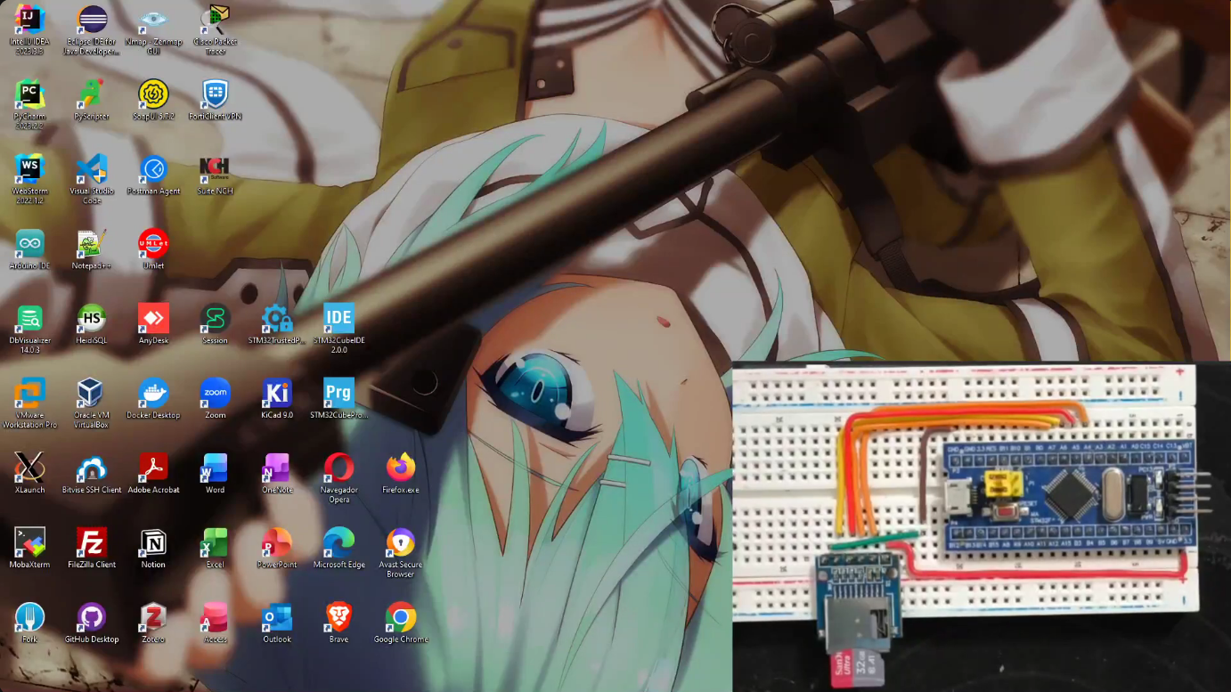
/pentesting_rd_pocPoC DocumentationBelow you can watch a short video demonstrating the PoC in action.
The complete documentation is available inside the /docs folder:
script.txt file.STM32CubeMX: Recommended to use the latest available version (tested with v6.16.0).
Download from the official ST website: https://www.st.com/en/development-tools/stm32cubemx.html
STM32CubeIDE: Recommended to use the latest available version (tested with v2.0.0).
Download from the official ST website: https://www.st.com/en/development-tools/stm32cubeide.html
KiCad: PCB design done using KiCad 9.0.
script.txt file.Future updates may include:
Distributed under the MIT License. See LICENSE.txt for more information.
Email: eloyschmidtrodriguez@gmail.com
LinkedIn: https://www.linkedin.com/in/eloyalfredoschmidtr/
Project Link: https://github.com/51n0nGG0/pentesting_rd
| Qty | Value | Footprint | References |
|---|---|---|---|
| 7 | 100nF | Capacitor_SMD:C_0402_1005Metric | C1, C2, C3, C4, C5, C7, C10 |
| 5 | 10k | Resistor_SMD:R_0402_1005Metric | R1, R2, R3, R4, R5 |
| 2 | 1uF | Capacitor_SMD:C_0402_1005Metric | C8, C9 |
| 1 | 10uF | Capacitor_SMD:C_0603_1608Metric | C6 |
| 1 | 500mA | Fuse:Fuse_0603_1608Metric | F1 |
| 1 | MOLEX_48037-1000 | MOLEX_48037-1000:MOLEX_48037-1000 | J1 |
| 1 | STM32F042C6T6 | Package_QFP:LQFP-48_7x7mm_P0.5mm | U1 |
| 1 | SW_Push | Button_Switch_SMD:SW_SPST_B3U-1000P | BOOT1 |
| 1 | TF-01A | TF-01A:TF-01A | MICRO_SD1 |
| 1 | USBLC6-2SC6 | Package_TO_SOT_SMD:SOT-23-6 | U2 |
| 1 | XC6206P332MR-G | Package_TO_SOT_SMD:SOT-23-3 | U3 |


fdiwth/tvc-drone
This repository contains the documentation, hardware designs, and source code for a Thrust Vector Control (TVC) drone.

jlcjak/astra_piNas
Six-layer CM5 Lite dual-NVMe carrier with PCIe switch, Ethernet, microSD, USB-C PD and PoE. Review design; fabrication hold documented.

beewarden/BeeFASYER_SPARROW
Each BEEFASYER monitoring network is centered on exactly one Sparrow.

It measures 19 × 44 mm and has 2 copper layers, 1.6 mm thick.
22 parts, built around the STM32F042C6T6, TF-01A, USBLC6-2SC6 and XC6206P332MR-G. The full list of its parts is on this page, with links to each part's symbol and footprint where PCBKit's library has them.
From the 51n0nGG0/pentesting_rd repository on GitHub, at the commit this page was made from: the board is pentesting_rd_schematics/pentesting_rd_schematics.kicad_pcb and its schematic pentesting_rd_schematics/pentesting_rd_schematics.kicad_sch. PCBKit opens the board in the browser, with nothing to install.
Its repository publishes it under the MIT licence: you may reuse it on that licence's terms (keep the author's notice, and for a copyleft licence share your changes alike).