2 layers101.6 × 53.4 mm

 4rynv/VacDepoctrl1
Open source firmware for a automation of vacuum systems controlled using Raspberry pi
Raspi HAT is an open-source printed circuit board by 4rynv, from the 4rynv/VacDepoctrl repository on GitHub. It is a 2-layer board of 65 × 76 mm with 36 parts on 57 nets.
It is built around the LM358, CAT24C256LI and BC847B, with the 1N4148W among its other parts. Its parts include 13 resistors, 9 connectors, 3 ICs, 2 diodes and 2 transistors.


A Raspberry Pi-based vacuum process controller. The current process is DC magnetron sputter deposition — chamber pump-down, argon gas flow, plasma ignition, and sputtering via a live Tkinter GUI with scrolling sensor graphs and a hardware-interlocked state machine. A thermal evaporation mode is planned as a second process on the same rig control stack.
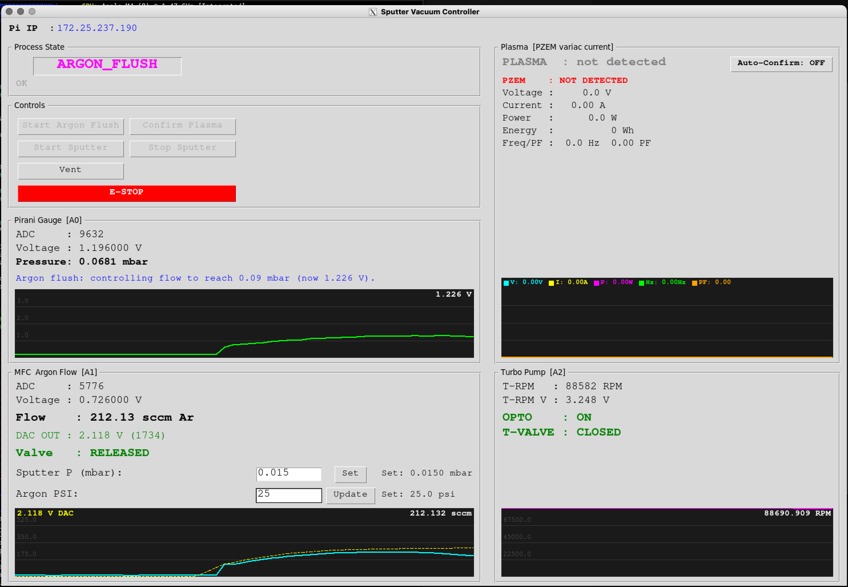
| Component | Model | Interface | Notes |
|---|---|---|---|
| Microcontroller | Raspberry Pi 5 (BCM GPIO) | — | Host for all control logic |
| Pirani gauge | ACE Instruments DHPG-015 | Analog 0–10V | Divided to 0–3.3V before ADC (ratio 0.33) |
| ADC | ADS1115 | I2C bus 1 @ 0x48 | Pirani on A0 (divided), MFC feedback on A1 (divided), turbo RPM tach on A2 |
| MFC | MKS 1179A | Analog 0–5V setpoint | 0–700 sccm Argon |
| DAC | MCP4725 | I2C bus 1 @ 0x60 | Level-shifted to the MFC's full 0–5V setpoint range — see below |
| DAC buffer | LM358P op-amp | Analog | Buffers + level-shifts the DAC output up to 0–5V; DAC alone cannot drive the MFC setpoint input |
| Turbo enable | Opto-isolator (4N35) | GPIO 17 (BCM, phys 11) | Marginal — needs BC547 output buffer, see below |
| MFC valve close | Emergency shut | GPIO 27 (BCM, phys 13) | Pulls MFC valve closed on demand |
| Turbo inlet valve | Relay via BC547 | GPIO 22 (BCM, phys 15) | HIGH = valve OPEN, LOW = valve CLOSED (relay NC contact) |
| Energy meter | PZEM-004T-100A | Modbus-RTU over CP2102 USB-TTL, /dev/ttyUSB0 | AC voltage/current/power on the variac output; plasma-ignition sensing. Optional at startup — see below |
Full 40-pin header and device wiring diagram
| Function | BCM GPIO | Physical header pin | Connection |
|---|---|---|---|
| I2C1 SDA | GPIO2 | 3 | ADS1115 SDA + MCP4725 SDA |
| I2C1 SCL | GPIO3 | 5 | ADS1115 SCL + MCP4725 SCL |
| Signal ground | — | 6 (or another GND) | ADC/DAC signal ground |
| Turbo enable | GPIO17 | 11 | Opto-isolator input circuit |
| MFC emergency close | GPIO27 | 13 | Existing MFC valve-close interface |
| Turbo inlet valve | GPIO22 | 15 | BC547 relay-driver input |
GPIO23/24 (physical pins 16/18) are no longer the I2C connection.
The Pi 5 uses hardware I2C1 at 100 kHz. Configure /boot/firmware/config.txt:
dtparam=i2c_arm=on
dtparam=i2c_arm_baudrate=100000| Signal | BCM | Physical pin |
|---|---|---|
| SDA | GPIO 2 | 3 |
| SCL | GPIO 3 | 5 |
| GND | Ground | 6 |
Connect both ADS1115 and MCP4725 to this bus; keep pull-ups at 3.3 V.
Power down before moving SDA/SCL from the previous GPIO23/24 wiring.
The code uses ExtendedI2C(I2C_BUS_NUMBER) with I2C_BUS_NUMBER = 1.
The older software-bus setup was a workaround for reported damaged GPIO2/3
on a previous setup; this configuration assumes functioning GPIO2/3.
Reboot after changing boot configuration; the operator performs device checks
and the first controller launch with equipment in a safe condition.
The DHPG-015 outputs 0–10V. A 3-resistor voltage divider scales this to 0–3.3V for the ADS1115 (divider ratio 0.33). All pressure thresholds in config.py are expressed in post-divider (ADC-side) volts. The full manufacturer calibration table lives in hardware/datasheets/Di-Hi-Pr-Pirani output voltage.pdf and is transcribed as _PIRANI_CAL in main.py.
The MCP4725 cannot source enough current to drive the MFC setpoint input directly — above ~1.25V the output voltage collapses under load even though it reads correctly when unloaded. An LM358P stage buffers the DAC output and shifts it up to the MFC's full 0–5V setpoint range before it reaches the MFC (ARGON_DAC_VREF = 5.0 in config.py reflects this — commanded flow covers the full 0–MFC_FULL_SCALE range, not a fraction of it):
DAC OUT ──────────────┬──── LM358 IN+ (pin 3)
                       │
                  (feedback) IN- (pin 2) ──── OUT (pin 1) ──── MFC setpoint
LM358 VCC (pin 8) ── Pi 5V
LM358 GND (pin 4) ── GND
Power the op-amp from the Pi's 5V rail, not 3.3V. The diagram above shows the original current-buffer wiring; the gain-setting feedback network that shifts the output up to 0–5V isn't captured in this ASCII diagram.
The turbo inlet solenoid valve (~50 mA @ 25–26 V) is switched by a relay, driven by a BC547:
GPIO22 ──470Ω── base   BC547   collector ── relay coil ── +5V
                          emitter ── GND         ▲
                                          1N4007 across coil
                                          (band toward +5V)

Valve circuit ── relay COM + NC contacts (isolated from the Pi)_poll(), turbo_valve_step()): valve held CLOSED at all times; latched OPEN during VENTING once turbo pump RPM (tach on ADC A2, see Turbo Pump RPM) sustains TURBO_VALVE_CONFIRM_SAMPLES consecutive reads at or below TURBO_VALVE_OPEN_RPM_MAX (35000 RPM); re-closed automatically on leaving VENTING. The debounce prevents a single corrupted I2C read from opening the valve; the latch prevents relay chatter once open. Driven by rotor speed directly rather than inferring it from chamber pressure — the earlier pressure-based gate (TURBO_VALVE_OPEN_MBAR) has been replaced.T-VALVE : CLOSED / OPEN (venting)).TURBO_RPM_VOLTAGE_FULL_SCALE, TURBO_RPM_FULL_SCALE), read by TurboRPMController (turbo_rpm.py) every poll tick regardless of state.T-RPM, T-RPM V, a scrolling RPM graph, plus OPTO and T-VALVE state — both turbo-side actuators, moved here from the Pirani panel) — below the Plasma panel, beside the Pirani/MFC panels.VENTING_PUMP_OFF_PROMPT_RPM (2000), the Pirani panel's status message turns orange and prompts the operator to turn off the primary/roughing pump — an early, informational cue, not a gate. The actual gate on completing the vent is separate — see Vent Completion Confirmation below.Reaching atmospheric pressure during VENTING does not by itself complete the vent. Earlier, sm.update() transitioned VENTING → IDLE purely from Pirani voltage — but the turbo inlet valve closes the instant the state leaves VENTING (turbo_valve_step()), so that auto-transition could reclose the valve before the operator had any real chance to react to the "turn off the primary pump" cue above, let alone actually do it.
VENTING → IDLE is now owned exclusively by _poll() (the same ownership pattern as ARGON_FLUSH → PLASMA_IGNITING), gated by vent_complete_ready(): both atmospheric pressure and an explicit operator click are required.
VENTING_COMPLETE_VOLTAGE during VENTING, _state["vent_complete_pending"] latches True — the Pirani panel's status message turns red ("Atmosphere reached — turn OFF the primary/roughing pump, then click Confirm Pump Off") and a Confirm Pump Off button appears in Controls (hidden otherwise, same show/hide pattern as Clear Fault)._state["vent_complete_confirmed"]; _poll() picks this up on its next tick and, if pressure is still at/above atmosphere, transitions to IDLE — closing the turbo inlet valve as part of the normal VENTING-exit path.handle_hardware_interlocks()), so a stale confirmation from a previous cycle can never auto-complete the next one.Reads AC voltage/current/power/energy/frequency/power-factor on the sputtering supply's variac output and uses the current-draw step when the discharge strikes to detect plasma ignition. Talks Modbus-RTU over a CP2102 USB-TTL adapter plugged into the Pi's USB port (pzem_meter.py) — a completely separate transport from the ADS1115/MCP4725 I2C bus above.
[!warning] Mains AC hazard The PZEM's voltage-sense terminals and current-transformer (CT) clamp are on live mains-derived AC, not the Pi's low-voltage side. Work de-energized (variac and upstream breaker off), verify with a meter before touching any terminal, don't work alone, and don't exceed the CT's 100A rating. The PZEM's internal isolation protects the TTL/USB side from the AC side once wired correctly — it does not protect you while wiring it.
AC side (mains, de-energized while wiring):
TTL side (isolated, low-voltage, safe to wire live):
| PZEM TTL pin | CP2102 pin | Notes |
|---|---|---|
| 5V | 5V | PZEM-004T v3.0's TTL interface requires 5V — verify the CP2102's voltage-select jumper (if it has one) is set to 5V, not 3.3V |
| GND | GND | Common ground |
| TXD | RXD | Cross — PZEM transmits into the adapter's receive pin |
| RXD | TXD | Cross — PZEM receives from the adapter's transmit pin |
Plug the CP2102 into any Pi USB port. It enumerates as /dev/ttyUSB0 (check with ls /dev/ttyUSB*; use a /dev/serial/by-id/... symlink instead if more than one USB-serial device is ever attached). The Pi user needs the dialout group to access it without root:
sudo usermod -a -G dialout $USER
# log out and back in for the group change to take effectModbus-RTU, 9600 baud 8N1, factory-default slave address 0xF8. pzem_meter.py hand-rolls the request framing and CRC16 (matching how mfc_control.py hand-rolls the MCP4725 I2C write) rather than pulling in a general Modbus library — reads input registers 0x0000–0x0009 (voltage, current, power, energy, frequency, power factor, alarm) every poll tick.
Optional hardware, unlike the ADS1115/MCP4725 checked in _startup_self_test(): this sensor may not be wired up yet. PZEMController.read() never raises — if the serial port can't be opened or the meter doesn't respond, it returns ready=False and a zeroed reading. main.py's two PZEM cross-sensor checks (below) only evaluate if e["ready"], so nothing they do can fire until the meter is actually installed and responding — deploying this code cannot regress a rig that doesn't have the PZEM wired yet.
plasma_detect_step() applies the same debounced ON/OFF hysteresis pattern as the turbo enable opto (TURBOOPTO_ON/OFF_THRESHOLD) to the PZEM's current reading: PZEM_PLASMA_CURRENT_ON_A (default 1.0A, unvalidated placeholder) held for PZEM_PLASMA_CONFIRM_SAMPLES (3) consecutive ticks latches plasma_detected True; it clears immediately below PZEM_PLASMA_CURRENT_OFF_A (0.6A). Like every other cross-sensor threshold in this repo, these must be bench-measured against the real supply's no-load vs. struck-plasma current before they mean anything.
plasma_detected drives the Plasma GUI panel (replacing the old placeholder) and the PLASMA_IGNITING → SPUTTER_READY confirmation, which now has three paths:
| Path | Trigger | Default |
|---|---|---|
| Manual | Operator clicks Confirm Plasma | Always available |
| Hybrid cue | Confirm Plasma button highlights green once plasma_detected is True during PLASMA_IGNITING — operator still clicks | Always on |
| Auto-confirm | Operator arms the Auto-Confirm toggle in the Plasma panel; while armed, a confirmed detection advances the state machine the same way a manual click would, via the same _complete_plasma_confirmation() path | Off by default |
Auto-confirm is an explicit operator opt-in, not the default, because PZEM_PLASMA_CURRENT_ON_A is unvalidated — the same reasoning as every other "unvalidated until confirmed on the bench" threshold in config.py. PLASMA_IGNITING's own PLASMA_IGNITION_TIMEOUT abort-to-READY path is unchanged and still the fallback if neither manual nor auto-confirm fires.
PLASMA_IGNITING → SPUTTER_READY succeeded, then pzem_plasma_absent_check() force-shut-down 5s later with the PZEM reporting 0.00 A the entire time. A true zero (not "some current below 1.0A") points at the sensor path, not calibration — most likely the CT clamp isn't actually installed on the load line yet (this repo's CT bring-up was still pending a bench test on the real variac-output load as of the prior session), or is clamped over both L and N together (fields cancel to ~0A), rather than L alone.N × I_actual on the reading — useful because a 100A-rated core sensing a sub-1A sputtering load sits at the very bottom of its response curve, where accuracy/noise floor issues are common. Divide the reported current/power by N in software to recover the true value, or (simpler, since only the comparison matters) scale PZEM_PLASMA_CURRENT_ON_A/_OFF_A by N instead. Sanity-check the real current independently first (a separate clamp meter, or the sputtering supply's own front-panel readout) before deciding how many turns to use.Every threshold elsewhere in this doc compares one sensor to one fixed value. These instead compare two live readings to each other — catching a case where each reading is individually "in range" but the two together don't make physical sense. All feed the global safety gate below: a sustained flag forces a full hardware cutoff, not just a status message. Grace periods are placeholder defaults (favor fewer false positives over noise from normal settling time) — tune once measured against real spin-up/response/settling behavior on the bench. Because a false positive forces a real shutdown, treat these as unvalidated until confirmed on the bench.
| Check | Compares | Flags when | Config |
|---|---|---|---|
turbo_spinup_check() | Turbo enable opto (GPIO 17) vs turbo RPM (ADC A2) | Opto commanding the turbo on for TURBO_SPINUP_GRACE_SECONDS (60s) while RPM stays below TURBO_RPM_STALL_THRESHOLD (10000) — turbo/RPM-sensor/wiring fault, or the turbo never spun up at all | config.py |
turbo_rpm_drop_check() | Same opto/RPM pair, but tracks a confirmed-healthy peak | RPM has exceeded TURBO_RPM_STALL_THRESHOLD at least once (confirmed healthy spin), then drops back below it for TURBO_RPM_DROP_GRACE_SECONDS (10s) while opto is still on — a running turbo failing/degrading, distinct from "never spun up" | config.py |
mfc_flow_check() | Commanded flow (DAC/flow_target) vs measured flow (A1 feedback) | Commanded ≥ MFC_FLOW_MIN_COMMANDED_SCCM (20) but measured stays below MFC_FLOW_RESPONSE_FRACTION (0.2×) of commanded for MFC_FLOW_GRACE_SECONDS (5s) — MFC not responding, dead unit, or empty gas supply | config.py |
dac_saturation_flow_check() | DAC output voltage vs measured flow | DAC pegged within DAC_SATURATION_MARGIN_V (0.1V) of ARGON_DAC_VREF while measured flow stays below DAC_SATURATION_FLOW_FRACTION (0.5×) of MFC_FULL_SCALE, for DAC_SATURATION_GRACE_SECONDS (10s) — the PID has given up on proportional correction and is commanding max output with nothing coming back: stuck valve, blocked line, or empty supply. A stronger signal than mfc_flow_check alone | config.py |
pressure_convergence_check() | Current Pirani voltage vs the active PID target (flush/sputter) | |current - target| exceeds PRESSURE_CONVERGENCE_TOLERANCE_V (0.3V) for PRESSURE_CONVERGENCE_GRACE_SECONDS (90s) despite the control loop running — leak, stuck valve, or MFC fault. Raised from 20s after a bench run showed a legitimate large setpoint step (e.g. PLASMA_IGNITING → SPUTTER_READY) needs longer than that to converge given the deliberately gentle PID tuning | config.py |
pzem_plasma_absent_check() | Process state (SPUTTER_READY/SPUTTERING only) vs PZEM plasma_detected | In SPUTTER_READY or SPUTTERING — both assume plasma is already lit — with no PZEM-confirmed current draw for PZEM_PLASMA_ABSENT_GRACE_SECONDS (5s): an arc dropout or the plasma extinguishing mid-run. PLASMA_IGNITING is deliberately excluded (PLASMA_IGNITION_TIMEOUT already owns "never struck"). Only evaluated once the PZEM is ready — see Energy Meter section above | config.py |
pzem_power_unexpected_check() | Process state (everywhere except PLASMA_IGNITING/SPUTTER_READY/SPUTTERING) vs PZEM plasma_detected | Plasma-level current draw while nowhere near attempting ignition (IDLE/PUMP_DOWN/READY/ARGON_FLUSH/VENTING) for PZEM_POWER_UNEXPECTED_GRACE_SECONDS (5s) — stuck relay, live supply, or wiring fault. Only evaluated once the PZEM is ready | config.py |
All are pure functions (main.py, next to turbo_valve_step()) — no I/O, no wall-clock access internally (the current timestamp is passed in), so they're tested directly like the calibration/valve logic.
Everything above this point in the doc is a local mechanism: a specific check for a specific failure, conditioned on which state you're in. The global gate is different — evaluated every poll tick regardless of current state, and any single condition tripping it forces the exact same full cutoff: turbo valve closed (direct GPIO write), MFC flow/valve/opto off, state forced to IDLE (sm.emergency_stop()), and the trip latches (see below).
| Condition | Detects | Config |
|---|---|---|
| Sustained cross-sensor flag | Any of the checks above, once their own grace period elapses | see table above |
sensor_range_check() | Any ADC-derived voltage (Pirani, MFC feedback, turbo tach) outside SANE_VOLTAGE_MIN/SANE_VOLTAGE_MAX for SENSOR_RANGE_CONFIRM_SAMPLES (5) consecutive ticks — disconnected, shorted, or miswired sensor, not a legitimate reading at any pressure/flow/speed. Suppressed for STARTUP_GRACE_SECONDS (5s) after the poll loop starts — real analog settling transients (MFC feedback observed at -0.15 to -0.23V for a few seconds after power-on) tripped this otherwise | config.py |
| Consecutive poll-loop exceptions | CONSECUTIVE_EXCEPTION_LIMIT (5) ticks in a row raise — occasional I2C/EMI glitches are tolerated (as before), but this many in a row is a real fault, not noise. Also suppressed during STARTUP_GRACE_SECONDS | config.py |
| Heartbeat / watchdog | The GUI thread (_refresh()) checks _state["last_tick"]; if the poll loop hasn't updated it within HEARTBEAT_TIMEOUT_SECONDS (2.0s), the poll thread is presumed stalled/hung. Checked from the GUI thread specifically — a hung poll thread can't detect its own hang | config.py |
All of this routes through _force_safe_shutdown(reason) (main.py) — safe to call every tick for as long as a condition persists (GPIO/state-machine calls are idempotent; _set_error() de-dupes the repeated log line rather than spamming it). handle_hardware_interlocks()'s own mfc/pirani cutoffs are already exception-safe (SputterStateMachine catches callback errors internally), so the only extra guarding needed is around the direct turbo-valve GPIO write, in case the poll thread hung mid-I2C-transaction.
The trip latches — a bench run found why this matters. emergency_stop() alone forces IDLE, but IDLE's own auto-resume-to-PUMP_DOWN logic (_poll()) will immediately re-enter PUMP_DOWN if pressure is already low (e.g. an external roughing pump already has the chamber down) — silently undoing the shutdown within one tick, with the process continuing as if nothing happened. _force_safe_shutdown() now sets _state["safety_tripped"], which blocks that auto-resume and shows a red banner + "Clear Fault" button in the Process State panel, plus a one-time modal alert. The IDLE branch checks this flag before its auto-transition. Clearing does not reset the underlying check's own "since" timer — if the root cause is still present, it re-trips immediately on the next tick. That's intentional: acknowledging a fault without fixing it must not let the process quietly continue.
Runs once before the poll thread starts (_startup_self_test(), main.py): re-validates config invariants at runtime (config_sanity_failures() — same checks as TestConfigSanity, but live, so a bad future edit to config.py is caught before the app runs with a broken safety threshold; this is exactly the class of bug that shipped once, VENTING_COMPLETE_VOLTAGE at ~5 mbar instead of near-atmosphere), and confirms the ADS1115 and MCP4725 DAC actually ACK on the I2C bus. Any failure prints to console and exits — no GUI exists yet at this point in startup.
Every operator-visible error/warning and every state transition is appended to sputter_ctrl.log (next to main.py, EVENT_LOG_FILENAME in config) via _log_event() — the GUI status bar only shows the latest message and auto-expires it after ERROR_DISPLAY_SECONDS, so this is the only place an incident can be reconstructed after the fact. _set_error() is the single choke point every error message goes through (writes _state["error"] and logs, de-duping repeats); handle_hardware_interlocks() logs every transition unconditionally, regardless of which state it's entering.
Do not drive relay coils or solenoids from a 4N35 directly — see the hard-won rule below.
A 4N35's usable output current is roughly CTR (~100%) × LED current (~10 mA max from a GPIO) ≈ 10 mA. Asked for more, it goes linear and drops the supply across itself (looks like a mystery series resistor). Loads measured on this rig:
| Load | Draw | 4N35 alone? |
|---|---|---|
| Turbo enable input | ~15–30 mA | No — needs BC547 buffer (pending) |
| Relay coil (5V) | ~60 mA | No — driven by BC547 directly, opto not needed (relay contacts provide the isolation) |
| Inlet solenoid | ~50 mA @ 26V | No — relay contacts switch it |
The turbo enable opto (GPIO 17) currently only works with excess LED drive; the proper fix is a BC547 buffer on its output (opto pin 5 → enable+, pin 4 → BC547 base, 10 kΩ base–emitter, BC547 C/E across the enable terminals). Flyback diodes go in parallel across coils (reverse-biased), never in series.
main.py
├── Hardware init (GPIO, ExtendedI2C bus 1, ADS1115)
├── Shared state dict (thread-safe, _lock)
├── Polling thread (_poll) — runs every POLLING_INTERVAL (0.2s)
│   ├── Reads Pirani + MFC + turbo RPM (A2) + PZEM (variac current) sensors
│   ├── Drives MFC pressure PID loop
│   ├── Drives turbo inlet valve latch (GPIO 22), gated on turbo RPM (not pressure)
│   ├── Debounced plasma_detect_step() from PZEM current -> plasma_detected
│   ├── Auto-confirms PLASMA_IGNITING -> SPUTTER_READY if the operator has
│   │   armed Auto-Confirm and plasma_detected is True
│   ├── Calls sm.update() for auto-transitions
│   ├── Converts Pirani voltage <-> mbar via log-linear calibration table
│   ├── End-of-tick safety cutoff re-assert (E-STOP race guard)
│   └── Updates shared state dict
├── Tkinter GUI (main thread)
│   ├── _refresh() — runs every GUI_REFRESH_INTERVAL (200ms) via root.after()
│   ├── Scrolling graphs (ScrollingGraph)
│   ├── Live pressure readout in mbar (adc_voltage_to_mbar)
│   ├── Manual set-point entry fields (sputter target mbar, argon PSI)
│   ├── Error display with ERROR_DISPLAY_SECONDS auto-expiry
│   └── Button callbacks → shared _try_*() operator commands
├── Web dashboard server (daemon threads — web_ui.py, see Web Dashboard)
│   ├── GET /events — SSE stream of _state snapshots to each browser
│   └── POST /command — dispatches the SAME _try_*() operator commands
└── Hardware interlock callback
    └── handle_hardware_interlocks() — fires on every state transition
The polling thread and GUI thread never share objects directly — all data passes through _state dict protected by _lock. On window close, _stop_event is set and the polling thread is joined (2 s timeout) before hardware shutdown and GPIO.cleanup().
E-STOP race guard: the poll loop reads the state once per tick; if an E-STOP/vent transition lands mid-tick, the interlock callback's cutoff could be overwritten by in-flight valve_release()/set_flow() calls. The poll loop therefore re-asserts the full safety cutoff at the end of any tick in which the state machine moved to IDLE/VENTING — the cutoff is always the last hardware write of the tick.
Error handling: errors are no longer cleared by the polling loop each tick. They persist in the status bar for ERROR_DISPLAY_SECONDS (10 s) and then auto-expire, so both operator-guard messages and the plasma-timeout message are actually readable.
VacDepoctrl/
├── main.py            — Entry point: GUI, polling thread, hardware init, cal table
├── config.py          — All constants, thresholds, and pin assignments
├── state_machine.py   — SputterStateMachine class (future: per-process state machines)
├── drivers/           — one class per hardware device
│   ├── mfc_control.py — MFCController class (DAC, valve, PID loop)
│   ├── pirani.py      — PiraniController class (ADC, turbo enable opto)
│   ├── turbo_rpm.py   — TurboRPMController class (ADC A2 tach → RPM)
│   └── pzem_meter.py  — PZEMController class (PZEM-004T-100A, Modbus-RTU over USB-TTL)
├── ui/
│   ├── graph.py       — ScrollingGraph class (pure Tkinter, no matplotlib; single/dual/multi-series)
│   ├── web_ui.py      — browser dashboard server (stdlib HTTP + SSE), parallel to the Tkinter GUI
│   └── web/
│       └── index.html — the dashboard page (self-contained: inline CSS/JS, no CDN)
├── sim/
│   └── sim_hardware.py — ChamberSim + fake hardware modules for SPUTTER_SIM=1 (Simulation Mode)
├── hardware/
│   ├── Raspi_HAT/     — KiCad project for the custom Raspberry Pi HAT (schematic/PCB/BOM)
│   └── datasheets/    — Pirani gauge output-voltage table PDF
├── docs/              — GUI screenshot and other README assets
├── assets/            — desktop/app icon source (app-icon*.png, AppIcon.icns)
├── scripts/
│   ├── setup.sh       — venv + dependency installer, also installs the desktop launcher
│ ├── VacDepoctrl.desktop — desktop launcher icon (installed by setup.sh; see Installation) pressure rises
┌─────────────────────────────┐
▼ │
IDLE ──(pressure drops)──► PUMP_DOWN ──(vacuum reached + opto)──► READY
▲ │ │
│ pressure rises [Start Argon Flush]
│ │ ▼
└─────────────────────────────┘ ARGON_FLUSH
│
(0.09 mbar reached)
▼
PLASMA_IGNITING
│ │
[Confirm Plasma] (2 min timeout)
│ │
▼ ▼
SPUTTER_READY READY
│
[Start Sputter]
▼
SPUTTERING
│
[Stop Sputter]
▼| From | To | Condition | Where |
|---|---|---|---|
IDLE | PUMP_DOWN | Pirani voltage ≤ 2.71V (10 mbar) | _poll() |
PUMP_DOWN | IDLE | Pirani voltage ≥ 2.71V (pump failure/leak) | _poll() + sm.update() |
PUMP_DOWN | READY | Voltage ≤ 0.3V AND opto enabled | sm.update() |
READY | PUMP_DOWN | Pirani voltage ≥ 2.71V (pressure degraded) | sm.update() |
ARGON_FLUSH | PLASMA_IGNITING | Voltage ≥ 1.287V (0.09 mbar) | _poll() only — sole owner: arms the ignition timeout and fires _ignite_plasma() |
PLASMA_IGNITING | READY | 120s timeout, no plasma confirmation | _poll() |
PLASMA_IGNITING | SPUTTER_READY | PZEM confirms plasma-level current draw, only if the operator has armed Auto-Confirm | _poll() — see Energy Meter |
VENTING | IDLE | Pirani voltage ≥ 3.0V (near-atmosphere) AND operator has clicked Confirm Pump Off | _poll() only — see Vent Completion Confirmation |
PLASMA_IGNITING → SPUTTER_READY is operator-driven by default (Confirm Plasma button, highlighted once the PZEM confirms detection) with an explicit opt-in Auto-Confirm toggle for the sensor-driven path — see the Energy Meter section for why auto-confirm defaults off. VENTING → IDLE similarly requires an explicit operator click regardless of pressure — there is no auto-confirm option for this one, since it's gating a real physical action (turning off the primary pump), not just a detection threshold.
| Button | Transition | Guard |
|---|---|---|
| Start Argon Flush | READY → ARGON_FLUSH | Argon inlet ≥ 15 psi |
| Confirm Plasma | PLASMA_IGNITING → SPUTTER_READY | None |
| Start Sputter | SPUTTER_READY → SPUTTERING | Argon inlet ≥ 15 psi |
| Stop Sputter | SPUTTERING → VENTING | None |
| Vent | PUMP_DOWN, READY, ARGON_FLUSH, PLASMA_IGNITING, SPUTTER_READY, SPUTTERING → VENTING | None — PUMP_DOWN added 2026-07-12 (previously only IDLE→PUMP_DOWN→IDLE was reachable from PUMP_DOWN; vent is now available mid-pump-down too) |
| Confirm Pump Off | VENTING → IDLE | Only appears once atmosphere is reached; see Vent Completion Confirmation |
| E-STOP | Any → IDLE | None — immediate. Routes through _force_safe_shutdown(): closes the turbo valve by direct GPIO write (no dependency on the poll thread being alive) and latches — Clear Fault required to resume, like a real EMO reset |
handle_hardware_interlocks() fires synchronously on every state transition:
mfc.set_flow(0), mfc.valve_close(), pirani.set_opto(False), and resets plasma_ignition_start / plasma_ignition_triggered so the next flush cycle starts clean (a stale flag previously could leave PLASMA_IGNITING with no armed timeout)pirani.set_opto(False) — resets opto for next pump-down cycleDuring VENTING the poll loop additionally holds the MFC valve closed every tick (venting is done with the turbo inlet valve, not through the MFC).
All voltages are post-divider (ADC input, ×0.33 from raw gauge output). Conversion between Pirani voltage and mbar uses log-linear interpolation against the full manufacturer calibration table (_PIRANI_CAL in main.py, source PDF in hardware/datasheets/): linear in voltage, logarithmic in pressure, matching the gauge's thermal-conductivity response. Both directions are implemented (mbar_to_adc_voltage, adc_voltage_to_mbar) and round-trip to machine precision at all 51 table points.
| Pressure (mbar) | Raw gauge (V) | ADC input (V) | Significance |
|---|---|---|---|
| 999 | 10.00 | 3.30 | Atmosphere (ADC saturated) |
| ~213 | — | 3.0 | VENTING_COMPLETE_VOLTAGE — VENTING → IDLE (safety margin below the 3.30V atmosphere point so the transition reliably fires) |
| 10 | 8.20 | 2.706 | IDLE_PRESSURE_MAX_VOLTAGE — pump-down gate |
| 0.09 | 3.90 | 1.287 | ARGON_FLUSH_TARGET_VOLTAGE — plasma ignition pressure |
| ~0.183 | 4.24 | 1.4 | Turbo enable opto fires (PUMP_DOWN, transition-based; raised from 1.3V 2026-07-12) |
| ~0.0057 | 0.91 | 0.3 | PUMP_DOWN_COMPLETE_VOLTAGE — PUMP_DOWN → READY gate (raised from 0.2V 2026-07-12) |
| 0.007 | 1.10 | 0.363 | 0.007 mbar — default sputtering pressure |
The GUI displays live pressure in mbar (bold, under the voltage readout), computed via adc_voltage_to_mbar(); reads ATM (>999 mbar) at ADC saturation.
An input field sets the SPUTTER_READY / SPUTTERING target pressure directly in mbar (default 0.007). Entered values are converted to an ADC voltage target via the calibration table before being passed to pressure_control_step().
Validated at entry: must be > 0 and ≤ SPUTTER_TARGET_MAX_MBAR (0.05 mbar). Values above the cap are rejected with a warning dialog rather than silently accepted — this also catches an Argon PSI value (tens) fat-fingered into this field, since any such value is far above the cap. Similarly, the Argon PSI field rejects anything below ARGON_PRESSURE_MIN_PSI (15 psi) with a warning, catching a Sputter P mbar value entered in the wrong field.
Transition-based, not level-based:
PUMP_DOWN (raised from 1.3V 2026-07-12)TURBOOPTO_ON_THRESHOLD/TURBOOPTO_OFF_THRESHOLD in config.py (ADC-count based, ~1.31V/~1.87V) — those drive pirani.py's auto_opto=True hysteresis path used in READY/ARGON_FLUSH, a different code path from this PUMP_DOWN transition-based one. The two are not currently kept in sync; only the PUMP_DOWN threshold above was changed this session.ssh av@<pi-ip>
git clone https://github.com/<your-username>/VacDepoctrl.git ~/VacDepoctrl
cd ~/VacDepoctrlWire physical pins 3/5 as described above. Enable these settings under [all]
in /boot/firmware/config.txt, removing any old i2c-gpio overlay:
dtparam=i2c_arm=on
dtparam=i2c_arm_baudrate=100000
The operator should reboot when safe, then verify /dev/i2c-1 exists.
Hardware verification should find ADS1115 at 0x48 and MCP4725 at 0x60.
Do not launch the controller until the wiring and equipment are ready:
main.py configures outputs immediately and can automatically enter PUMP_DOWN.
cd ~/VacDepoctrl
chmod +x scripts/setup.sh
./scripts/setup.sh
This installs adafruit-blinka, adafruit-circuitpython-ads1x15, adafruit-extended-bus, rpi-lgpio (providing the RPi.GPIO API), and pyserial into a venv at ~/VacDepoctrl/venv/, adds a source_vacdep alias to ~/.bashrc, and places a VacDepoctrl icon on the desktop (VacDepoctrl.desktop) — double-click it to launch main.py directly, no terminal needed. First launch may need a one-time "Allow Launching" confirmation (right-click the icon → Allow Launching) depending on the desktop environment's trust settings for new .desktop files.
source ~/.bashrc
source_vacdepIf the PZEM-004T-100A / CP2102 is wired up (see Energy Meter), add the Pi user to dialout so main.py can open /dev/ttyUSB0 without root:
sudo usermod -a -G dialout $USER
# log out and back in for the group change to take effect
This step can be skipped entirely — the meter is optional hardware and main.py starts normally without it (see pzem_meter.py).
Must be run on the Pi with a display connected (HDMI or VNC), not over a plain SSH session.
source_vacdep
cd ~/VacDepoctrl
python main.py
Note: use
python, notpython3, inside the activated venv on this setup.
To run over SSH with display forwarding:
ssh -X av@<pi-ip>
source_vacdep && cd ~/VacDepoctrl && python main.py
This renders the GUI on your own machine instead of the Pi's local display — see Remote GUI Access below for one-time setup and why you'd want to.
Bench-test scripts (run these with main.py stopped — they fight over pins):
python tests/adc_test.py          # live ADC readings, both channels
python tests/dac_test.py          # DAC voltage staircase + register readback
python tests/opto_test.py         # GPIO 17 toggle every 5 s
python tests/turbo_valve_test.py # GPIO 22 relay/valve toggle every 5 sWhy: Raspberry Pi OS Bookworm's default desktop uses a Wayland compositor
(labwc). On older/weaker boards that compositor can
alone consume most of the CPU just keeping the desktop alive — independent of
main.py — which shows up as system-wide lag, including the mouse cursor
itself stuttering. Tkinter also doesn't speak Wayland natively; on this
desktop it runs through an Xwayland compatibility shim that gets composited
by labwc anyway, adding a second layer of overhead on top.
SSH X11 forwarding (ssh -X) sidesteps all of that: main.py still runs
on the Pi (it has to — that's where the GPIO/I2C/PZEM-over-USB hardware
physically is), but the X11 protocol (drawing commands, not rendered
frames) is tunneled to an X server running on your own machine, which does
the actual rendering. None of the Pi's local compositor is involved. This is
optional — if you're on the Pi's physical HDMI display or VNC and it isn't
laggy for you, there's nothing to set up.
The Pi side needs no configuration — sshd already has X11Forwarding yes
and xauth installed. Every OS below needs its own X server to receive
the forwarded connection, since none of them speak X11 out of the box.
./scripts/setup_remote_gui_macos.shOr manually:
brew install --cask xquartz
open -a XQuartz
Then from a new terminal (so it picks up XQuartz's environment):
ssh -X av@<pi-ip>
source_vacdep && cd ~/VacDepoctrl && python main.py
If the window doesn't appear, try -Y (trusted forwarding, fewer
restrictions) instead of -X. Still nothing? As a last resort:
defaults write org.macosforge.xquartz.X11 nolisten_tcp -bool falsethen quit and relaunch XQuartz. This allows raw TCP connections to the X
server, not just the local Unix socket ssh -X normally uses — a real
(if small, loopback-only-by-default) security tradeoff, so it's not applied
automatically by the script above; only turn it on if the standard path
above doesn't work.
Desktop launcher (optional): once XQuartz is set up, ./scripts/build_mac_launchers.sh
builds two double-clickable .app icons on the Desktop — the Mac
equivalent of VacDepoctrl.desktop on the Pi:
RIGS in scripts/build_mac_launchers.sh and rebuild
to add more — one entry auto-connects with no prompt, several show a
choose-from-list dialog), then runs the ssh -X command above for you.
Connects via the Pi's mDNS hostname (av.local) rather than a raw IP —
DHCP has moved this rig's address before, but the mDNS name survives
that. The SSH password itself is left to ssh's own normal interactive
Terminal prompt (secure, no extra tooling) rather than something like
sshpass.Both open Terminal.app rather than running silently, since main.py's
startup self-test prints failures to the console before any GUI window
exists — same reasoning as Terminal=true in the Pi's .desktop file.
First launch of either needs a one-time right-click → Open to bypass
Gatekeeper's unsigned-app warning.
[!note] Live network discovery was tried and doesn't work here mDNS service browsing (
dns-sd -B _ssh._tcp) was the first approach tried for "find the Pi automatically" — it doesn't find this rig, since Avahi on the Pi isn't advertising_ssh._tcp(only plain hostname resolution works, which is whatav.localabove relies on). A maintained list is simply more reliable than scanning here.
Two options — pick one:
localhost:0) before connecting.Either way, once connected: source_vacdep && cd ~/VacDepoctrl && python main.py.
Usually nothing to install. A native X11 desktop session supports ssh -X
out of the box; a Wayland desktop on Linux ships Xwayland by default too
(unlike macOS/Windows, which have no X server at all). Just:
ssh -X av@<pi-ip>
source_vacdep && cd ~/VacDepoctrl && python main.pyAny browser on the LAN gets the full live interface — readouts, graphs, and controls — at:
http://av.local:8080 (or http://<pi-ip>:8080)No app, no XQuartz, no SSH, no per-OS setup; works from a phone. Served by
ui/web_ui.py (stdlib HTTP + Server-Sent Events — nothing to install) with the
page in ui/web/index.html (self-contained, no CDN: renders on a LAN with no
internet).
Parallel by design, never a replacement. The web dashboard is a second
view of the same running main.py — the local Tkinter GUI always runs
regardless (WEB_UI_ENABLED only controls the browser side). A network
problem can therefore only ever cost the browser page; the control loop and
the local GUI on the rig don't know or care whether anyone is connected. The
page makes staleness unmissable: if the stream stops for >3 s it greys out
behind a DISCONNECTED banner rather than silently showing frozen numbers.
Commands are the same code path as the local buttons. Every browser
action dispatches the exact _try_*() function the corresponding Tkinter
button calls — same argon-pressure guards, same state-machine locks, same
confirmation gates (Confirm Plasma, Confirm Pump Off, Clear Fault). Every
web command is appended to sputter_ctrl.log with the client's IP, so the
audit trail records who did what from where.
[!warning] No authentication Anyone on the LAN who can reach port 8080 can operate the rig — the same trust model as the Pi's own VNC/SSH access. Don't expose the Pi to a network you don't control; set
WEB_UI_ENABLED = Falseinconfig.pyto not open the port at all.
Troubleshooting: browsers with HTTPS-Only mode (Firefox especially)
rewrite a bare <ip>:8080 to https:// and fail with
SSL_ERROR_RX_RECORD_TOO_LONG — the server is plain HTTP, so the URL must
start with an explicit http://. The Tkinter header shows the full URL in a
selectable field with a Copy button for exactly this reason.
[!warning] Deploy this feature as a set, not piecemeal
WEB_UI_ENABLEDlives inconfig.py, but the code it depends on (ui/web_ui.py,ui/web/index.html) are separate files. A partialscpthat ships aconfig.pywithWEB_UI_ENABLED = Truebut not the other two crashesmain.pyon startup withModuleNotFoundError: No module named 'web_ui'— every launch path fails identically (desktop icon, SSH -X, plain SSH), since the crash happens at import time before Tkinter ever gets a chance to open a window. Hit and fixed 2026-07-12. Always deployconfig.pytogether with the wholeui/folder, or setWEB_UI_ENABLED = Falseon the Pi if you're deliberately deploying without the dashboard for now.
Runs the full GUI and control loop — state machine, PID loop, cross-sensor checks, plasma detection — on any machine with no Pi, no sensors, and no GPIO/I2C/serial hardware attached. Useful for developing/demoing this project, or just poking at the UI without risking anything.
SPUTTER_SIM=1 python main.py
# or
python main.py --sim
sim/sim_hardware.py installs fake RPi.GPIO / adafruit_ads1x15 /
adafruit_extended_bus / serial modules into sys.modules before
main.py's own hardware imports run (the same technique the hardware-free
test suite uses) — but unlike the test suite's static, manually-set values,
these are backed by a live physics model (ChamberSim) that reacts to
whatever the real control loop actually commands: turbo RPM ramps when the
enable opto goes high, pressure falls while pumping and rises when the
turbo valve opens or the MFC commands flow, MFC measured flow chases
commanded flow with a lag, etc. The window shows an unmissable orange
"SIMULATION MODE" banner so it's never confused with a real run.
Plasma strikes are manual, not automatic. An early version auto-triggered
the simulated variac current from a flow+low-pressure heuristic, but that
fired during ARGON_FLUSH itself — before any real ignition attempt, since
the PID legitimately drives flow/pressure into the same range just
converging on the flush target. _ignite_plasma() is still a stub on real
hardware too, so nothing should auto-decide this in the simulation either.
Instead, Simulation Mode adds a "Plasma Strike (SIM)" toggle button to
the Controls panel — click it whenever you want to simulate the plasma
actually igniting; it stays exactly as set until toggled again.
On macOS, ./scripts/build_mac_launchers.sh builds a double-clickable
VacDep Simulation.app — see Remote GUI Access above.
All tunable parameters are in config.py. Key constants:
# I2C
I2C_BUS_NUMBER               = 1       # hardware I2C1 on GPIO2/3
ADS1115_I2C_ADDRESS          = 0x48
ARGON_DAC_I2C_ADDRESS        = 0x60

# GPIO (BCM)
GPIO_PIRANI_PIN              = 17      # turbo enable opto
GPIO_MFC_VALVE_CLOSE_PIN     = 27      # emergency valve close
GPIO_TURBO_VALVE_PIN         = 22      # turbo inlet valve relay (was GPIO 4 — dead pad)

# Pressure thresholds (post-divider volts unless noted)
IDLE_PRESSURE_MAX_VOLTAGE    = 2.71    # 10 mbar  — pump-down gate
PUMP_DOWN_COMPLETE_VOLTAGE   = 0.3     # PUMP_DOWN → READY gate
ARGON_FLUSH_TARGET_VOLTAGE   = 1.287   # 0.09 mbar — plasma ignition pressure
VENTING_COMPLETE_VOLTAGE     = 3.0     # VENTING → IDLE threshold (near-atmosphere; see Pressure Reference)
SPUTTER_TARGET_MAX_MBAR      = 0.05    # cap on the operator-settable Sputter P field
ARGON_PRESSURE_MIN_PSI       = 15.0    # floor on the operator-settable Argon PSI field

# Turbo pump RPM (tach on ADC A2) and inlet valve interlock
ADC_CHANNEL_TURBO_RPM        = 2
TURBO_RPM_VOLTAGE_FULL_SCALE = 3.3     # volts at A2 for full-scale RPM
TURBO_RPM_FULL_SCALE         = 90000.0 # RPM at full-scale voltage
TURBO_VALVE_OPEN_RPM_MAX     = 35000   # inlet valve opens once RPM drops to/below this
TURBO_VALVE_CONFIRM_SAMPLES = 3 # consecutive reads required before opening (debounce)Current tuned values (Kp=8, Kd=3) were arrived at empirically on hardware:
POLLING_INTERVAL from 0.5s to 0.2s, which made the derivative term ~2.5× more aggressive for the same physical Kd — gains must be retuned whenever POLLING_INTERVAL changes), Kd=7→3PRESSURE_CONTROL_ICLAMP). Setting Ki=0 while tuning is safe (no divide-by-zero).If you change POLLING_INTERVAL, expect to retune Kd and Ki — both depend on dt between samples.
| Element | Description |
|---|---|
| Pi IP | Live IP address shown in header |
| Process State | Current state, colour-coded |
| Safety Trip banner / Clear Fault | Appears (red) in the Process State panel only when the global safety gate has forced a shutdown; see Global Safety Gate. Clearing does not fix the underlying condition — an unaddressed fault re-trips immediately |
| Start Argon Flush | Opens MFC valve, starts PID loop to 0.09 mbar |
| Confirm Plasma | Manually confirms plasma ignition; transitions to SPUTTER_READY. Highlights green once the PZEM confirms plasma-level current draw during PLASMA_IGNITING |
| Auto-Confirm toggle | Plasma panel. Off by default. When armed, a PZEM-confirmed detection auto-advances PLASMA_IGNITING → SPUTTER_READY without a click — see Energy Meter |
| PLASMA / PZEM readout / graph | Plasma panel (replaces the old placeholder): live plasma_detected status, PZEM voltage/current/power/energy/frequency/power-factor, and one scrolling graph with a legend covering all but energy (shown as a numeric total instead) |
| Start Sputter | Begins sputtering from SPUTTER_READY |
| Stop Sputter | Ends sputtering, transitions directly to VENTING |
| Vent | Vents chamber to atmosphere |
| Confirm Pump Off | Hidden until atmospheric pressure is reached during VENTING; click completes the vent (closes the turbo inlet valve, transitions to IDLE) — see Vent Completion Confirmation |
| E-STOP | Immediate: kills flow, closes both valves (turbo valve by direct GPIO write — works even with a hung poll thread), drops opto, returns to IDLE and latches; Clear Fault to resume |
| Voltage + Pressure (mbar) | Live Pirani readings; mbar via log-linear calibration table |
| OPTO | Turbo Pump panel. Green = turbo enable opto on; Red = off |
| T-VALVE | Turbo Pump panel. Green CLOSED = inlet valve shut (normal); Orange OPEN (venting) = venting and turbo RPM has dropped to/below TURBO_VALVE_OPEN_RPM_MAX |
| T-RPM / T-RPM V / turbo graph | Own Turbo Pump panel (below Plasma, beside Pirani/MFC); turbo pump RPM (ADC A2), its raw ADC voltage, and a scrolling RPM graph, all read every tick |
| Sputter P (mbar) | Operator-set target pressure; press Set or Enter. Rejected (warning dialog) if ≤ 0 or > 0.05 mbar |
| Argon PSI | Operator-entered regulator pressure; ≥ 15 psi required for flush/sputter. Rejected (warning dialog) if < 15 psi |
| Pirani graph | Scrolling ADC voltage (lime, 0–4V, 60 samples) |
| MFC graph | Scrolling flow sccm (cyan) overlaid with DAC voltage (yellow dashed) |
| DAC OUT | Green = DAC found on I2C; Red = not detected |
| Valve | Green = released (MFC in control); Red = closed (emergency) |
| Status bar | Errors shown in red, auto-expire after 10 s |
_ignite_plasma() is a stub: RF power supply trigger is not yet implemented.PZEM_PLASMA_CURRENT_ON_A/OFF_A): guessed values, not yet measured against the real supply's no-load vs. struck-plasma current. This is why Auto-Confirm defaults off — see Energy Meter.pzem_plasma_absent_check(). Until the CT is verified clamped correctly on the live load conductor (and, if the real current is low relative to the CT's 100A rating, wound through with multiple turns — see Energy Meter bring-up notes), plasma auto-detection cannot be trusted; keep Auto-Confirm off and rely on the manual Confirm Plasma button.Goals only, near-term → eventual. Inspired in part by how production fabs structure tool control: hardwired interlocks under software, standardized state/alarm/recipe models (SECS/GEM), and fault detection built on ruthless data collection.
_force_safe_shutdown()), software
heartbeat/watchdog, startup self-test, persistent event log, config validation
at launch — implemented in software; not yet validated on hardware. Still
outstanding: a Pi-level hardware watchdog (/dev/watchdog, forced reboot if
unpetted) — deliberately deferred, separate systemd/infra decision with its
own tradeoffs (what state GPIOs land in across a forced reboot)sim/sim_hardware.py, SPUTTER_SIM=1 python main.py or --sim.
Extends the unit suite's static test fakes into a live interactive sim with a
simple first-order physics model (ChamberSim) that reacts to real GPIO/DAC/
serial writes from the actual control loop, not canned values_ignite_plasma() itself, with arc suppression confirmed in hardwareturbo_valve_step(), TURBO_VALVE_OPEN_RPM_MAX); not yet validated
against a real vent cycle on hardwaresecsgem Python library for a real SEMI E30 interface) so the
tool can be driven like production fab equipmentBlinka 9.2.0 declares a dependency on legacy RPi.GPIO. Setup installs Blinka
first, then replaces that package with rpi-lgpio for Pi 5 support. Do not
install both together. pip check currently reports Blinka's missing RPi.GPIO
distribution even though import RPi.GPIO is supplied by rpi-lgpio. Re-run
setup after dependency upgrades that reinstall the legacy package.
| Qty | Value | Footprint | References |
|---|---|---|---|
| 8 | 10k | Resistor_SMD:R_0805_2012Metric | R3, R4, R5, R6, R7, R8, R11, R12 |
| 4 | MountingHole_2.7mm_M2.5 | MountingHole:MountingHole_2.7mm_M2.5 | MH1, MH2, MH3, MH4 |
| 2 | 3.9k | Resistor_SMD:R_0805_2012Metric | R1, R2 |
| 2 | BC847B | Package_TO_SOT_SMD:SOT-23 | Q1, Q2 |
| 1 | 100n | Capacitor_SMD:C_0805_2012Metric | C1 |
| 1 | 1N4148W | Diode_SMD:D_SOD-123 | D2 |
| 1 | 20k | Resistor_SMD:R_0805_2012Metric | R13 |
| 1 | 330 | Resistor_SMD:R_0805_2012Metric | R10 |
| 1 | 470 | Resistor_SMD:R_0805_2012Metric | R9 |
| 1 | ADC1_Conn_01x10_Pin | Connector_PinSocket_2.54mm:PinSocket_1x10_P2.54mm_Vertical | J2 |
| 1 | CAT24C256 | Package_SO:SOIC-8_3.9x4.9mm_P1.27mm | U1 |
| 1 | DAC1_Conn_01x06_Pin | Connector_PinSocket_2.54mm:PinSocket_1x06_P2.54mm_Vertical | J3 |
| 1 | EL817 (SMD) | Package_SO:SO-4_7.6x3.6mm_P2.54mm | U2 |
| 1 | G5V-1 5V | Relay_THT:Relay_SPDT_Omron_G5V-1 | K1 |
| 1 | GPIO | Connector_PinSocket_2.54mm:PinSocket_2x20_P2.54mm_Vertical | J1 |
| 1 | ID_WP | Jumper:SolderJumper-2_P1.3mm_Open_TrianglePad1.0x1.5mm | JP1 |
| 1 | LM358 | Package_SO:SOIC-8_3.9x4.9mm_P1.27mm | U3 |
| 1 | M7 (1N4007) | Diode_SMD:D_SMA | D1 |
| 1 | MFC_JST | Connector_JST:JST_XH_B4B-XH-A_1x04_P2.50mm_Vertical | J9 |
| 1 | PIRANI_JST | Connector_JST:JST_XH_B2B-XH-A_1x02_P2.50mm_Vertical | J10 |
| 1 | RPM_JST | Connector_JST:JST_XH_B2B-XH-A_1x02_P2.50mm_Vertical | J11 |
| 1 | TURBO_EN | TerminalBlock_Phoenix:TerminalBlock_Phoenix_MKDS-1,5-2-5.08_1x02_P5.08mm_Horizontal | J6 |
| 1 | UART_JST | Connector_JST:JST_XH_B4B-XH-A_1x04_P2.50mm_Vertical | J8 |
| 1 | VALVE | TerminalBlock_Phoenix:TerminalBlock_Phoenix_MKDS-1,5-3-5.08_1x03_P5.08mm_Horizontal | J5 |
It measures 65 × 76 mm and has 2 copper layers, 1.6 mm thick.
36 parts, built around the LM358, CAT24C256LI, BC847B and 1N4148W. The full list of its parts is on this page, with links to each part's symbol and footprint where PCBKit's library has them.
From the 4rynv/VacDepoctrl repository on GitHub, at the commit this page was made from: the board is hardware/Raspi_HAT/Raspi_HAT.kicad_pcb and its schematic hardware/Raspi_HAT/Raspi_HAT.kicad_sch. PCBKit opens the board in the browser, with nothing to install.
Its repository states no licence, so its author keeps all rights: ask 4rynv before reusing the design.


Benv-B/photo-frame-hardware
Open hardware carrier for an AirDrop ChLCD color e-paper frame: XIAO ESP32-C5, NFC wake, KiCad, schematic, BOM and Gerbers. CERN-OHL-P-2.0.

pachobg2/moskvich_ignition
Programmable ignition ECU for Moskvich 412/2140 (ESP32-C3, web tuner)

PE1RGU/hf-antenna-switch
Remote HF antenna switch: 3 radios x 4 antennas (path to 8), outdoor relay unit with a hardware safety chain, controlled over Cat6 from a shack interface. KiCad 10, open hardware, designed together with an AI.


