4 layers76.9 × 67.3 mm

 4f48/battery-pico
A battery charger add-on board for all Raspberry Pi Pico development boards.
Battery pico is an open-source printed circuit board by 4f48, from the 4f48/battery-pico repository on GitHub, published under the CERN-OHL-S-2.0 licence. It is a 2-layer board of 21 × 20.9 mm with 14 parts on 16 nets, routed with 30 tracks and 5 vias.
It is built around the MCP73831T-2ACI/OT-HXY, AO3401A and RC0603FR-071K5L, with the CRCW0603100KFKEAC and LTST-C190KFKT among its other parts. Its parts include 3 resistors, 3 connectors, 2 capacitors, 2 transistors and 1 IC. It belongs with the power and microcontroller boards boards and the RP2040 boards of this library.


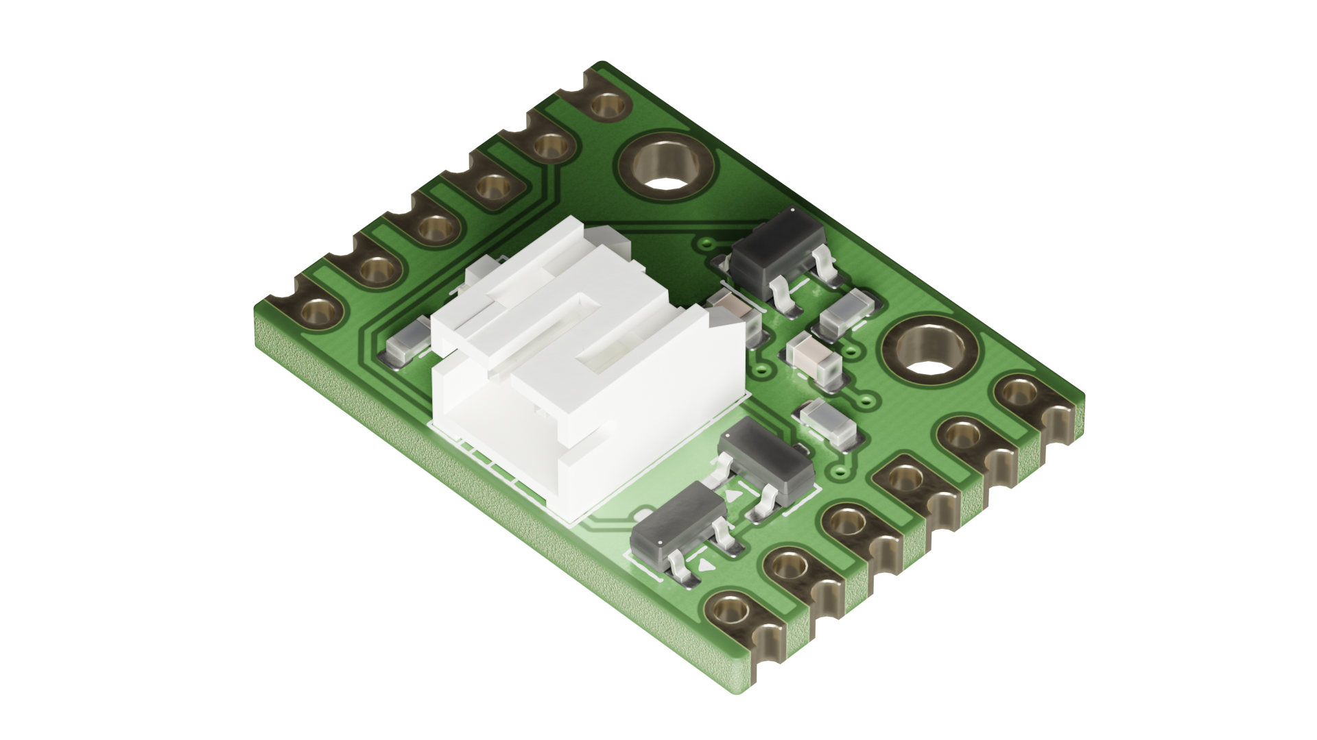
A Lithium-Polymer battery charger add-on board for all Raspberry Pi Pico development boards. It features 250 mA charging with power-path management and a JST PH battery connector, all while only spanning the first 6 rows of pins. The board has castellated pads and screw mounting, just like the Pico, so you can even use it standalone.
[!CAUTION] This board doesn't include battery protection circuitry. It is not safe for use with Lithium-Ion cells or unprotected Lithium-Polymer cells. Make sure your battery has built-in protection before connecting.
To get started, you'll need to solder the add-on board to the back of your Pico, with the JST PH connector facing away from the USB port. The text on the add-on board and the pin labels on the back of the Pico should be facing each other. The screw holes on the add-on card should align with the screw holes next to the USB port on the Pico.
You are basically done now. All you need to do is connect a battery to start using the battery charger add-on board. You can do so by getting a battery with a JST PH connector out of the box or soldering on a JST PH connector to the battery yourself.
You don't need any specific software for the battery add-on card to work.
Battery Pico's source files are publicly available on Codeberg and GitHub, licensed under CERN-OHL-S-2.0. The add-on board uses widely and cheaply available components and is designed in a way that it's easy to build it at home.
Since the board has castellated pads, you'll need to find a manufacturer who supports castellated pads/edges/holes. Aisler supports them free of charge, while at JLCPCB you'll have to pay extra to have them made.
| Reference | Qty | Value | MPN | Link |
|---|---|---|---|---|
| C1,C2 | 2 | 4.7u | GRM188Z71C475KE21D | https://www.tme.eu/hu/en/details/grm188z71c475ke21d/mlcc-smd-capacitors/murata/ |
| D1 | 1 | ORANGE | LTST-C190KFKT | https://www.tme.eu/hu/en/details/ltst-c190kfkt/smd-colour-leds/liteon/ |
| J3 | 1 | Conn_01x02 | S2B-PH-K-S (LF)(SN) | https://www.tme.eu/hu/en/details/s2b-ph-k-s/raster-signal-connectors-2-00mm/jst/s2b-ph-k-s-lf-sn/ |
| Q1,Q2 | 2 | AO3401A | AO3401A | https://www.tme.eu/hu/en/details/ao3401a/smd-p-channel-transistors/alpha-omega-semiconductor/ |
| R1 | 1 | 3.9k | CRCW06033K90FKTABC | https://www.tme.eu/hu/en/details/crcw06033k90fktabc/smd-resistors/vishay/ |
| R2 | 1 | 100k | CRCW0603100KFKEA | https://www.tme.eu/hu/en/details/crcw0603100kfkea/smd-resistors/vishay/ |
| R3 | 1 | 1.5k | RC0603FR-071K5L | https://www.tme.eu/hu/en/details/rc0603fr-071k5/smd-resistors/yageo/rc0603fr-071k5l/ |
| U1 | 1 | MCP73831-2-OT | MCP73831T-2ACI/OT | https://www.tme.eu/hu/en/details/mcp73831t-2aci_ot/battery-and-battery-cells-controllers/microchip-technology/ |
The components used on this board are widely available. Check out the BOM that includes manufacturer part numbers for each component. You can upload that to your favourite parts distributor's website. For Europe, you can easily buy all the components using the parts list from TME. Their shipping options are much better than DigiKey or Mouser.
Once you have your manufactured PCBs and the components, you'll need to assemble the PCB. For that, a fine-tipped soldering iron, solder of your choice and flux (optional, but helps) are needed.
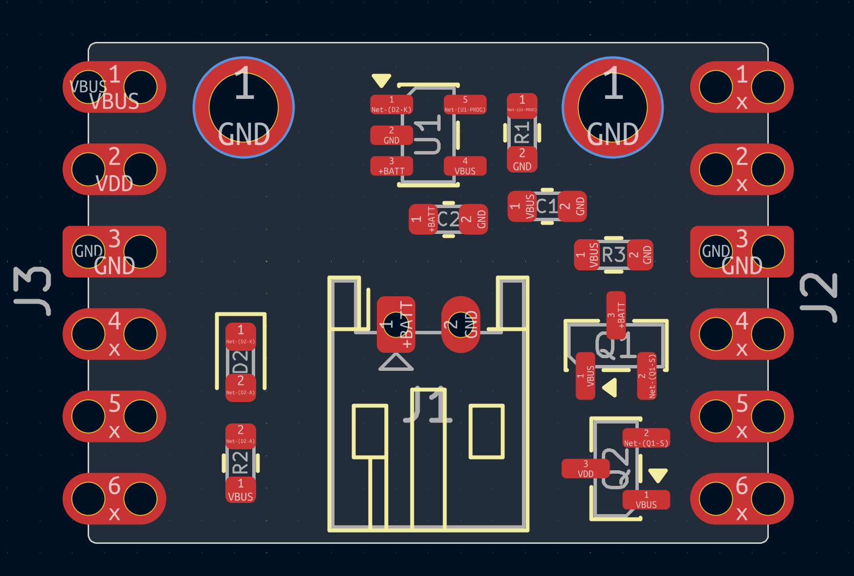
Refer to this image when placing the components on the board. You can match the reference values (e.g. U1, R2) with the BOM or the TME parts list. Where component orientation matters, pin 1 is marked with an arrow on the silkscreen.
For the JST PH connector, you may find using a larger-tipped soldering iron better.
This board isn't for everyone. Cheap Lithium-Polymer charger boards are everywhere, but the problem is that they are standalone, have a separate USB port, sometimes they are huge or unreliable.
The thing about the Raspberry Pi Pico is, that it's a very capable board, but in itself it's not useful for anything. You can use it to experiment on your desk, but once you want to do something serious, you often end up needing a battery. And while RP2040/RP235X-based third-party development boards exist, they are often very expensive.
The Battery Pico add-on board aims to bridge this gap by augmenting your cheap Pico with battery wizardry! You can make one cheaply and it doesn't take up too much extra space.
| Qty | Value | Footprint | References |
|---|---|---|---|
| 2 | 4.7u | Capacitor_SMD:C_0603_1608Metric | C1, C2 |
| 2 | AO3401A | Package_TO_SOT_SMD:SOT-23 | Q1, Q2 |
| 2 | Conn_01x06 | battery-pico:PinHeader_1x06_P2.54mm_Vertical_Castellated | J1, J2 |
| 2 | MountingHole_Pad | battery-pico:MountingHole_2.1mm_Pad_3mm | H1, H2 |
| 1 | 1.5k | Resistor_SMD:R_0603_1608Metric | R3 |
| 1 | 100k | Resistor_SMD:R_0603_1608Metric | R2 |
| 1 | 3.9k | Resistor_SMD:R_0603_1608Metric | R1 |
| 1 | Conn_01x02 | Connector_JST:JST_PH_S2B-PH-K_1x02_P2.00mm_Horizontal | J3 |
| 1 | MCP73831-2-OT | Package_TO_SOT_SMD:SOT-23-5 | U1 |
| 1 | ORANGE | LED_SMD:LED_0603_1608Metric | D1 |
It measures 21 × 20.9 mm and has 2 copper layers, 1.6 mm thick.
14 parts, built around the MCP73831T-2ACI/OT-HXY, AO3401A, RC0603FR-071K5L and CRCW0603100KFKEAC. The full list of its parts is on this page, with links to each part's symbol and footprint where PCBKit's library has them.
From the 4f48/battery-pico repository on GitHub, at the commit this page was made from: the board is pcb/battery-pico.kicad_pcb and its schematic pcb/battery-pico.kicad_sch. PCBKit opens the board in the browser, with nothing to install.
Its repository publishes it under the CERN-OHL-S-2.0 licence: you may reuse it on that licence's terms (keep the author's notice, and for a copyleft licence share your changes alike).


xmyoot/custom-round-pcb-led-flash
Custom circular ring PCB LED flash controller prototype


pluggee/piweather
raspberry pi based system for weather monitoring and automation

alphaseneca/chronopixel-pcb
Hardware design and KiCad PCB files for the ChronoPixel smart matrix desk clock.
