4 layers129.5 × 115.6 mm

 2tf2294x4g-maker/MacintoshPortable4MB_RAM3
A 4MB RAM board for the Macintosh Portable using 5V SRAM
PortableRAM-5V is an open-source printed circuit board by 2tf2294x4g-maker, from the 2tf2294x4g-maker/MacintoshPortable4MB_RAM repository on GitHub, published under the CERN-OHL-S-2.0 licence. It is a 4-layer board of 123 × 81 mm with 31 parts on 171 nets, routed with 4,091 tracks and 503 vias.
It is built around the 74HC245D and IS61WV5128BLL-10TLI. Its parts include 15 capacitors, 11 ICs, 3 resistors and 2 connectors. It belongs with the FPGA and CPLD boards of this library.


Expands a Macintosh Portable from 1 MB to 5 MB total (1 MB onboard + this 4 MB card).
This is a fully 5V design — no level shifters, no LDO regulator, no 3.3V rail. All parts are readily available and inexpensive. The board has been built and validated working in a real Mac Portable.
| Capacity | 4 MB (8× 512K×8 SRAM) |
| Bus width | 8-bit × 2 banks (addressed via CPLD) |
| Logic | ATF1502ASL CPLD (5V, TQFP-44) |
| SRAM | 8× AS7C4096A-12TCN (5V, TSOP-II-44) |
| Layers | 4 (F.Cu signal / GND plane / +5V plane / B.Cu signal + pour) |
| Connector | Samtec BCS-125-F-D-HE (50-pin 2×25, horizontal entry) |
| Ref | Qty | Value | Package | Part / Notes |
|---|---|---|---|---|
| U2–U9 | 8 | AS7C4096A-12TCN | TSOP-II-44 | Alliance Memory — 512K×8 5V SRAM 12 ns |
| U1 | 1 | ATF1502ASL | TQFP-44 | Microchip ATF1502ASL-25AU44 — must be ASL (5V), not ASV |
| U11, U12 | 2 | 74HC245 | SOIC-20 wide | SN74HC245DW — verify wide (7.5 mm) body |
| J1 | 1 | RAM connector | Samtec BCS-125-F-D-HE | 50-pin socket, horizontal entry — free Samtec sample |
| J2 | 1 | JTAG header | 1×6 2.54 mm pin header | Pin 1 (square pad) = TCK |
| C1–C12 | 12 | 100 nF | 0805 | X7R 50V ceramic bypass |
| C13–C15 | 3 | 10 µF | 0805 | X5R 16V ceramic bulk |
| R2–R4 | 3 | 10 KΩ | 0805 | 5% thick film |
Full BOM with Mouser/DigiKey part numbers: BOM.csv
PortableRAM-5V.kicad_pcb     — PCB layout (KiCad 9)
PortableRAM-5V.kicad_sch     — Schematic
PortableRAM-5V.kicad_pro     — Project file
PortableRAM.kicad_sym        — Custom symbol library
PortableRAM.pretty/          — Custom footprint library
Gerbers/                     — Gerber + drill files (ready to order)
Gerbers.zip                  — Same, zipped (upload directly to fab)
firmware/
  PortableRAM.pld            — CUPL source (ATF1502ASL logic)
  PortableRAM.jed            — Compiled JEDEC
  PortableRAM.svf            — SVF for OpenOCD programming
  program.sh                 — One-command programming script (Tigard)
BOM.csvUpload Gerbers.zip to your preferred fab (JLCPCB, PCBWay, OSHPark, etc.).
Board settings:
Solder in this order to keep the board flat and iron access clear:
C14 and C15 look different — they are 10 µF (larger value) vs. the surrounding 100 nF caps. Value is printed on the back silkscreen.
The ATF1502ASL must be programmed before the card will work. Use J2 (the 1×6 header on the board edge).
| Pin | Signal |
|---|---|
| 1 | TCK |
| 2 | TMS |
| 3 | TDI |
| 4 | TDO |
| 5 | +5V |
| 6 | GND |
Set the Tigard voltage jumper to 5V before connecting.
cd firmware
./program.sh
The script runs:
openocd -f interface/ftdi/tigard.cfg \
  -c "transport select jtag; adapter speed 200; reset_config none" \
  -c "jtag newtap atf1502 tap -irlen 10 -expected-id 0x0150203f" \
  -c "init; svf PortableRAM.svf; shutdown"
Success output ends with shutdown command invoked and no TDO mismatch errors.
Use firmware/PortableRAM.jed directly. Any ISP tool that supports ATF1502ASL JTAG programming will work.
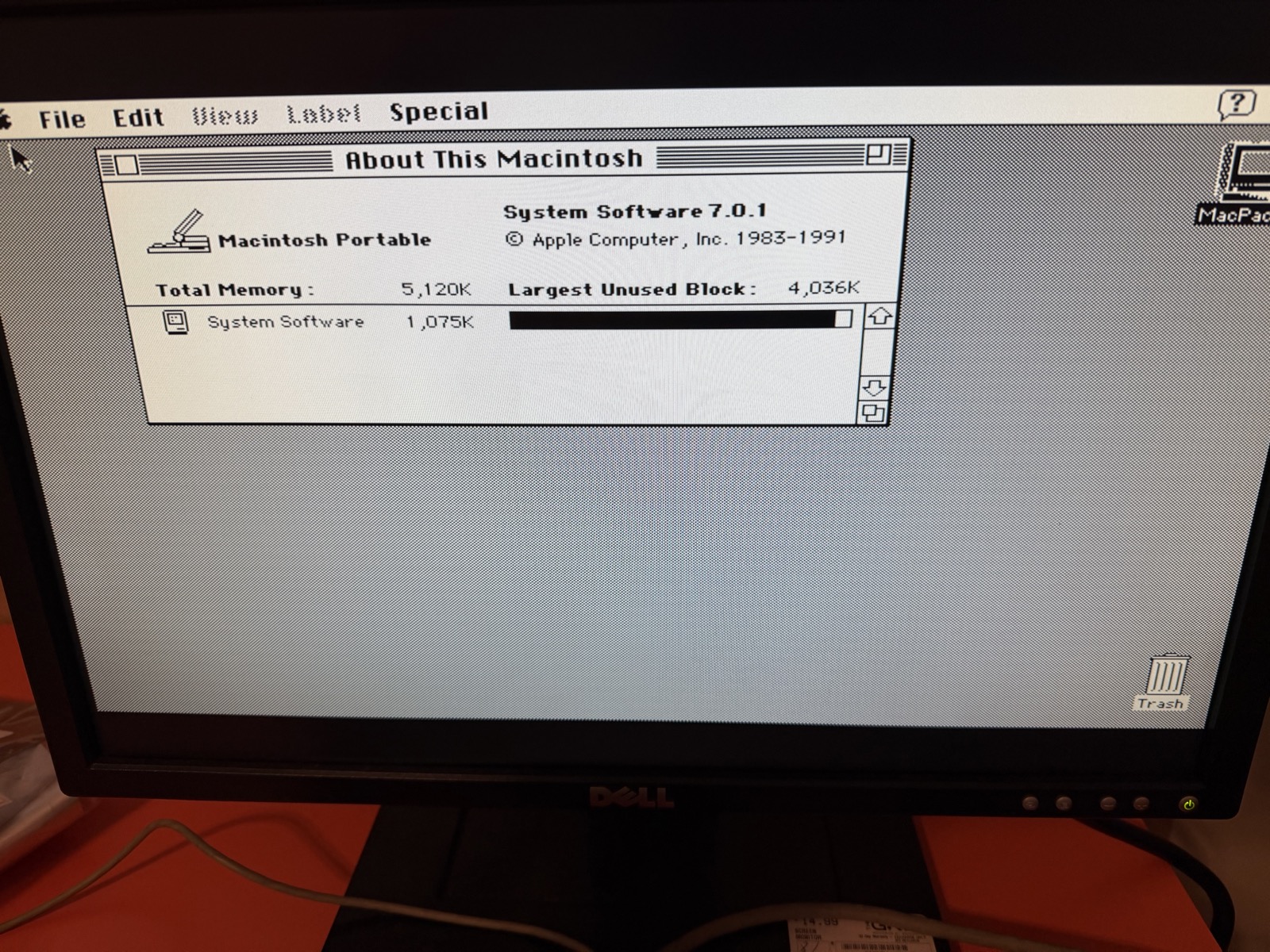
The Portable's memory manager will detect the expanded RAM automatically. You should see 5 MB in About This Macintosh (1 MB onboard + 4 MB this card).
firmware/PortableRAM.pld (CUPL).These are the actual costs from the first build (v0.2, USA, mid-2026, including tariffs).
| 5× 4-layer boards | $30.40 |
| Shipping | $9.03 |
| Discount | −$5.73 |
| Tax | $2.40 |
| Payment fee | $0.50 |
| Total for 5 boards | $36.60 |
| Per board | ~$7.32 |
Ordered as 4-layer rigid, 1.6 mm, HASL. Minimum order is 5 boards at JLCPCB — extras make good spares or second builds.
| Part | Qty ordered | Unit | Ext |
|---|---|---|---|
| ATF1502ASL-25AU44 (CPLD) | 2 | $3.12 | $6.24 |
| SN74HC245DWR (74HC245 wide SOIC) | 4 | $0.75 | $3.00 |
| 100 nF 50V X7R 0805 | 50 | $0.07 | $3.35 |
| 10 µF 16V X5R 0805 | 10 | $0.46 | $4.60 |
| 10 KΩ 5% 0805 | 12 | $0.03 | $0.38 |
| Shipping + tax + tariff | $10.53 | ||
| Total | $28.10 |
Quantities cover two boards (v0.2 + planned 8MB build). Per-card share of this order is roughly $14.
| Part | Qty | Approx total |
|---|---|---|
| AS7C4096A-12TCN (5V SRAM) | 10 | ~$90 |
10 chips ordered; 8 needed per board. Per-card SRAM cost ~$72.
Free sample direct from Samtec (samtec.com → request a sample of BCS-125-F-D-HE). Allow 1–2 weeks. If purchasing, expect ~$8–12.
| Item | Approx cost |
|---|---|
| PCB (1 of 5 from JLCPCB) | $7 |
| 8× AS7C4096A SRAM | $72 |
| CPLD + transceivers + passives | $14 |
| Samtec J1 connector | free / ~$10 |
| Total | ~$93–103 |
The SRAM dominates the cost. Prices will vary by region, supplier, and tariff environment.
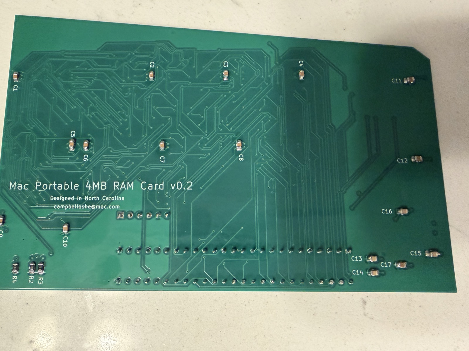
v0.2 is the validated, working board. It has been built, assembled, programmed, and confirmed running in a real Macintosh Portable showing 5,120K total memory. The files in this repo are based on v0.2 with the lessons learned applied.
| Front (component side) | Back (solder side) |
|---|---|
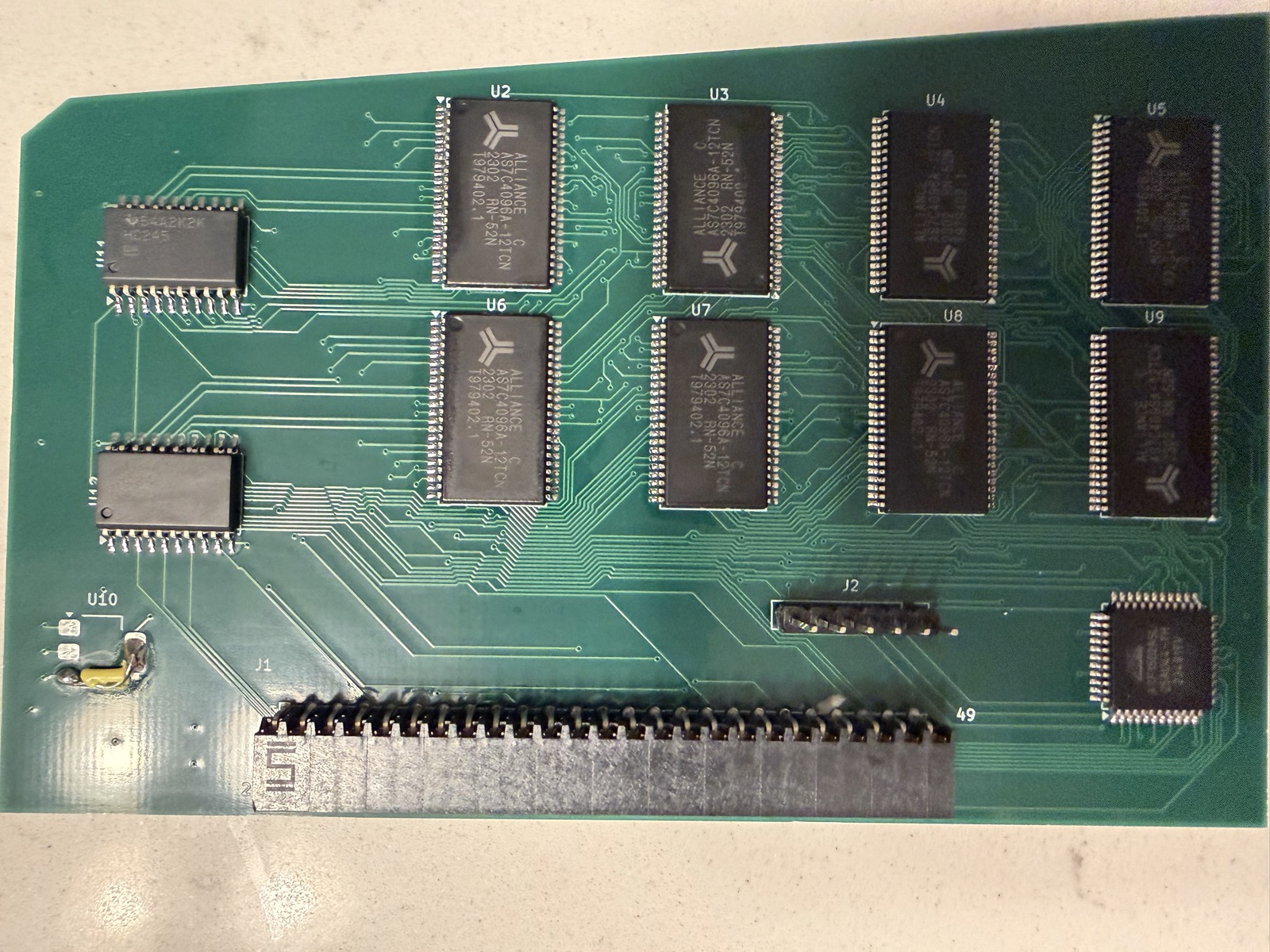 |  |
U10 (AMS1117-3.3 LDO regulator) — designed in, not needed, bodged out
The original v0.2 schematic included U10, an AMS1117-3.3 LDO to generate a 3.3V rail for what was originally planned as 3.3V SRAM with level shifters. During the build it became clear the design could run entirely at 5V using the AS7C4096A SRAM — no 3.3V rail needed at all. U10 was not installed; instead its VIN and VOUT pins were bridged with a wire (visible as the yellow bodge at the bottom-left of the front photo) to pass +5V through to the downstream circuitry that had been wired to the 3.3V net.
C15, C16 — bypass caps for U10, also unnecessary
Two 10 µF bulk caps (C15, C16 on v0.2, visible on the back) were the input and output bulk capacitors for the U10 LDO. With U10 gone they serve no purpose and were not installed.
Cap numbering — gaps in the sequence
After removing C15/C16, the original numbering left gaps (C13, C14, then C17). This made assembly confusing. On v0.3 the caps were renumbered C1–C15 sequentially.
v0.3 incorporates all the above fixes into a clean board:
Note: v0.3 has not been independently built and validated from scratch — it is a design cleanup of the proven v0.2. The logic, layout, and routing are unchanged from the working board; only the LDO circuitry was removed. If you build v0.3 and it works (or doesn't), please open an issue and let us know.
This card would not exist without the following prior work:
Dynamic Engineering Mac Portable RAM Card
The address decode and bus control logic in PortableRAM.pld is derived from the GAL22V10 PLD source files originally written for the Dynamic Engineering commercial RAM expansion card for the Mac Portable. These files define the core signal equations — bank chip-select generation, byte-lane write control via UDS*/LDS*, bus transceiver direction, and output enable timing. The original .PLD files were recovered and shared by techknight on the TinkerDifferent forum and #skunkworks Discord. Translated here from three GAL22V10 chips to a single ATF1502ASL CPLD, with corrections to the r_w_u equation and address decode base.
miejas — Macintosh Portable 4MB Memory Expansion https://github.com/miejas/Macintosh-Portable-4-MB-Memory-Expansion Open-source 4MB RAM card whose connector pinout, bus transceiver approach, and firmware structure were used as a cross-reference to validate signal assignments and confirm that AS* and SLEEP* are not present on the expansion connector.
Reza Fouladian — PortableRAM BGA 8MB https://github.com/rezafouladian/PortableRAM-BGA-8MB BGA-format 8MB card using the ATF1502ASV (3.3V CPLD) and SN74LVC4245A level translators. Used as a reference for address decode strategy and CPLD pin planning.
Apple Mac Portable Developer Notes & Schematics Apple's original hardware documentation for the Mac Portable expansion bus, memory map, and GLU register behaviour (including the $FC0200 DTACK register).
CERN-OHL-S-2.0PortableRAM.pld) — MIT · SPDX MITBoth licence texts are included in full in this repository. Do what you like — just share improvements.
| Qty | Value | Footprint | References |
|---|---|---|---|
| 13 | 100nF | Capacitor_SMD:C_0805_2012Metric | C1, C2, C3, C4, C5, C6, C7, C8, C9, C10, C11, C12, C13 |
| 8 | IS61WV5128BLL-10TLI | Package_SO:TSOP-II-44_10.16x18.41mm_P0.8mm | U2, U3, U4, U5, U6, U7, U8, U9 |
| 3 | 10K | Resistor_SMD:R_0805_2012Metric | R2, R3, R4 |
| 2 | 10µF | Capacitor_SMD:C_0805_2012Metric | C14, C15 |
| 2 | 74HC245 | Package_SO:SOIC-20W_7.5x12.8mm_P1.27mm | U11, U12 |
| 1 | ATF1502ASL | Package_QFP:TQFP-44_10x10mm_P0.8mm | U1 |
| 1 | JTAG_Header_2.54mm_1x06 | Connector_PinHeader_2.54mm:PinHeader_1x06_P2.54mm_Vertical | J2 |
| 1 | RAM Connector | PortableRAM:Samtec_BCS-125-F-D-HE | J1 |

slu4coder/Minimal-64x4-Home-Computer
My DIY TTL home computer with VGA and PS/2 and 4x the processing power of a Commodore C64 or Apple II.

slu4coder/Minimal-UART-Computer-1-2
Legacy: Version 1 and 2 of my TTL-only CPU featuring UART I/O, an expansion port, 512KB SSD at up to 10MHz clock speed

crmaykish/mackerel-68k
A series of single-board Motorola 68k computers with support for modern Linux

slu4coder/Minimal-64-Home-Computer
Legacy: Full TTL-only home computer with VGA and PS/2 and twice the processing power of a Commodore 64

Pixelvation/Pixelvation
This GitHub repository is the current home of Pixelvation and will be updated whenever there's some significant new development.

Board-Folk/MegaCD-Main-BD
Reproductions of main board PCBs for Sega's Mega CD/Sega CD add-on for the Mega Drive/Genesis console.

It measures 123 × 81 mm and has 4 copper layers, 1.63 mm thick.
31 parts, built around the 74HC245D and IS61WV5128BLL-10TLI. The full list of its parts is on this page, with links to each part's symbol and footprint where PCBKit's library has them.
From the 2tf2294x4g-maker/MacintoshPortable4MB_RAM repository on GitHub, at the commit this page was made from: the board is PortableRAM-5V.kicad_pcb and its schematic PortableRAM-5V.kicad_sch. PCBKit opens the board in the browser, with nothing to install.
Its repository publishes it under the CERN-OHL-S-2.0 licence: you may reuse it on that licence's terms (keep the author's notice, and for a copyleft licence share your changes alike).