Skip to the content
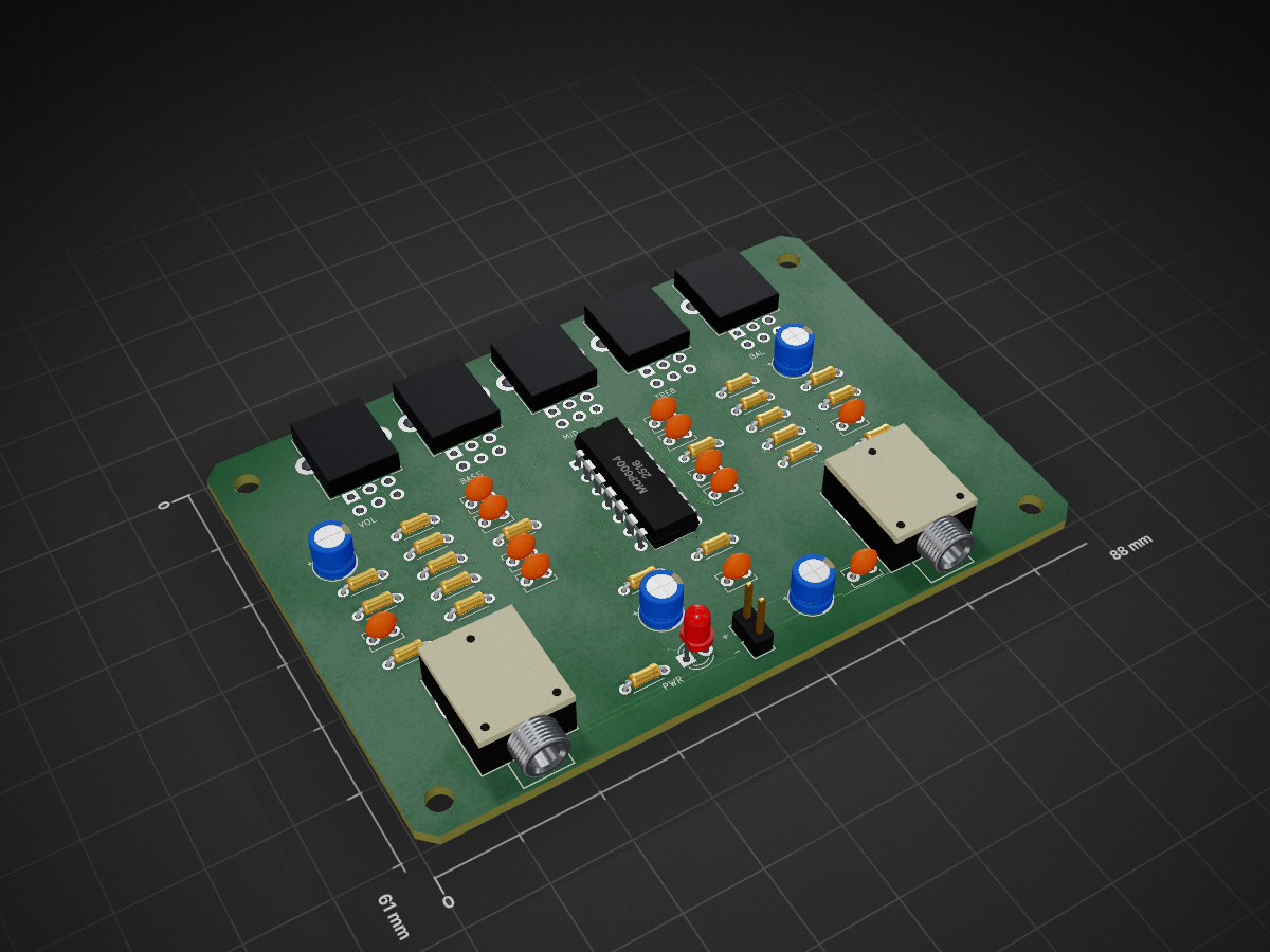
2 layers88 × 61 mmTht opamp eq, the printed circuit board in 3D

Autonomous, end-to-end KiCad PCB design skill for AI coding agents (Antigravity, Claude Code, Codex). Headless automation via kicad-cli & pcbnew, DRC verification, and JLCPCB manufacturing exports.

Size
88 × 61 mm
Copper layers
2
Thickness
1.6 mm
Parts
51
Nets
40
Pads
146
Tracks, vias
313, 11
Pours
1
Routed
Yes
KiCad
KiCad 9.0 (file 20241229)
Created
14 Sep 2026
Updated
15 Sep 2026

Overview

Tht opamp eq is an open-source printed circuit board by 1999AZZAR, from the 1999AZZAR/pcb-skill repository on GitHub, published under the MIT licence. It is a 2-layer board of 88 × 61 mm with 51 parts on 40 nets, routed with 313 tracks and 11 vias.

It is built around the MCP6004-E/P. Its parts include 3 connectors, 1 IC and 1 diode.

Main components

1

README

project/pcb/tht_opamp_eq/README.md

THT 3.3V Stereo 3-Band Equalizer & Preamp

An ultra-compact, high-fidelity, 100% Through-Hole (THT) stereo audio equalizer and headphone/line preamplifier designed for 3.3V battery or single-supply operation.

Zero surface-mount components. Optimized for hand soldering, DIY audio gear, portable headphone setups, and custom instrument tone shaping.


Highlights & Specifications

ParameterSpecificationDetails
Form Factor88.0 mm × 61.0 mmUltra-compact 2-layer PCB
Component Technology100% Through-Hole (THT)Easy hand assembly with basic iron
Supply Voltage3.3V DC (1.8V to 5.5V tolerated)Single-cell LiFePO4, 3.7V Li-Ion (via LDO), or 2x/3x AA
Active CoreMicrochip MCP6004 (DIP-14)Quad Rail-to-Rail I/O CMOS Op-Amp
Quiescent Current~3.0 mA total (including LED)Extremely power-efficient for battery use
Input / OutputDual 3.5 mm TRS Stereo JacksAC-coupled audio line & headphone drive
Tone ControlsBass, Mid, Treble (±10 to 12 dB)Active feedback Baxandall topology
Volume & BalanceLog Volume + Linear BalanceIndependent stereo level and stereo imaging
GroundingSolid B.Cu Ground PlaneFull ground pour for minimum hum and noise
Mounting4× M3 Mounting Holes4.0 mm inset from board corners
DRC Compliance0 Errors, 0 Warnings, 0 Unconnected Nets100% clean KiCad strict DRC pass

Circuit Architecture

text
[3.5mm Stereo IN] 
       │
       ▼ (1 µF AC Coupling)
[VOL Potentiometer (50k Log)] 
       │
       ▼
[Active 3-Band Baxandall Filter] ── MCP6004 (U1A / U1D)
  ├── BASS  (100k Linear) ~100 Hz shelf (±12 dB)
  ├── MID   (100k Linear) ~1.0 kHz band (±10 dB)
  └── TREB  (100k Linear) ~10 kHz shelf (±12 dB)
       │
       ▼
[BAL Potentiometer (100k Linear)] (Stereo cross-attenuation)
       │
       ▼
[Output Driver & Buffer Stage]   ── MCP6004 (U1B / U1C)
       │
       ▼ (100 µF AC Coupling + 47Ω isolation)
[3.5mm Stereo OUT]

1. Dual Rail-to-Rail Op-Amp (MCP6004 DIP-14)

  • Sections A & D: Left and Right inverting active tone stages. Placing the tone network in the negative feedback loop ensures low distortion and predictable boost/cut curves.
  • Sections B & C: Left and Right output driver stages configured for clean buffering with 47Ω series output resistors (R_STAB_L, R_STAB_R) to prevent oscillation when driving capacitive cables or low-impedance headphones.

2. Virtual Ground Bias (VBIAS)

  • Single-supply audio requires referencing AC signals to mid-rail ($V_{CC} / 2 = 1.65\text{ V}$).
  • Created by a low-noise resistive divider (R_BIAS1, R_BIAS2 = 100 kΩ) heavily decoupled by C_BIAS1 (47 µF electrolytic) and C_BIAS2 (100 nF ceramic).
  • Virtual ground connects to the non-inverting pins (Pins 3 and 12 of U1) with dedicated traces and zero ground loops.

3. Five Control Knobs (14.0 mm Pitch)

Five dual-gang Alpha RD902F vertical potentiometers line the top edge for convenient front-panel integration:

  1. VOL (RV1): 50 kΩ Dual Audio (Logarithmic) — Input gain and volume attenuation.
  2. BASS (RV2): 100 kΩ Dual Linear — Low-frequency shelf response.
  3. MID (RV3): 100 kΩ Dual Linear — Mid-frequency vocal and instrument presence.
  4. TREB (RV4): 100 kΩ Dual Linear — High-frequency air and sparkle.
  5. BAL (RV5): 100 kΩ Dual Linear — Left-to-Right stereo pan balance.

Bill of Materials (BOM)

All 51 components are through-hole parts readily sourced from LCSC, Mouser, Digikey, or local electronics suppliers:

DesignatorValueFootprint / PackageDescriptionQty
U1MCP6004-E/PDIP-14_W7.62mmQuad Rail-to-Rail I/O Op-Amp1
RV150k Dual Log (A50K)Potentiometer_Alpha_RD902F-40-00D_Dual_VerticalMaster Stereo Volume Control1
RV2100k Dual Lin (B100K)Potentiometer_Alpha_RD902F-40-00D_Dual_VerticalBass Control (±12 dB @ 100 Hz)1
RV3100k Dual Lin (B100K)Potentiometer_Alpha_RD902F-40-00D_Dual_VerticalMidrange Control (±10 dB @ 1 kHz)1
RV4100k Dual Lin (B100K)Potentiometer_Alpha_RD902F-40-00D_Dual_VerticalTreble Control (±12 dB @ 10 kHz)1
RV5100k Dual Lin (B100K)Potentiometer_Alpha_RD902F-40-00D_Dual_VerticalStereo Balance Control1
J13.5mm StereoJack_3.5mm_Ledino_KB3SPRS_HorizontalAudio Input TRS Jack1
J23.5mm StereoJack_3.5mm_Ledino_KB3SPRS_HorizontalAudio Output TRS Jack1
J32-pin 2.54mmPinHeader_1x02_P2.54mm_VerticalDC Power Input (Pin 1: +3.3V, Pin 2: GND)1
D13mm Green/RedLED_D3.0mmPower Indicator LED1
C_PWR1100 µF 16VCP_Radial_D5.0mm_P2.00mmMain Power Bulk Filter Capacitor1
C_PWR2100 nF 50VC_Disc_D3.8mm_W2.6mm_P2.50mmHigh-Frequency Power Decoupling1
C_BIAS147 µF 16VCP_Radial_D5.0mm_P2.00mmVirtual Ground (VBIAS) Bulk Filter1
C_BIAS2100 nF 50VC_Disc_D3.8mm_W2.6mm_P2.50mmVBIAS High-Frequency Bypass1
C_IN_L, C_IN_R1.0 µF 50VC_Disc_D3.8mm_W2.6mm_P2.50mmAudio Input DC-Blocking Capacitors2
C_OUT_L, C_OUT_R100 µF 16VCP_Radial_D5.0mm_P2.00mmAudio Output DC-Blocking Capacitors2
C_BASS_L1, C_BASS_R147 nFC_Disc_D3.8mm_W2.6mm_P2.50mmBass Filter Frequency Setting2
C_MID_L1, C_MID_R122 nFC_Disc_D3.8mm_W2.6mm_P2.50mmMidrange Filter Frequency Setting2
C_TREB_L1, C_TREB_L2, C_TREB_R1, C_TREB_R22.2 nFC_Disc_D3.8mm_W2.6mm_P2.50mmTreble Filter Frequency Setting4
R_BIAS1, R_BIAS2100 kΩ 1/4WR_Axial_DIN0207_L6.3mm_D2.5mm_P7.62mm_HorizontalVBIAS Voltage Divider (1% Tol)2
R_PWR1.0 kΩ 1/4WR_Axial_DIN0207_L6.3mm_D2.5mm_P7.62mm_HorizontalLED Current Limiter1
R_IN_L, R_IN_R100 kΩ 1/4WR_Axial_DIN0207_L6.3mm_D2.5mm_P7.62mm_HorizontalInput AC Coupling Bias Reference2
R_IN_EQ_L, R_IN_EQ_R10 kΩ 1/4WR_Axial_DIN0207_L6.3mm_D2.5mm_P7.62mm_HorizontalTone Stage Input Isolation2
R_FB_EQ_L, R_FB_EQ_R10 kΩ 1/4WR_Axial_DIN0207_L6.3mm_D2.5mm_P7.62mm_HorizontalTone Stage Feedback Loop Resistors2
R_BASS_L, R_BASS_R10 kΩ 1/4WR_Axial_DIN0207_L6.3mm_D2.5mm_P7.62mm_HorizontalBass Stage Shaping2
R_TREB_L, R_TREB_R4.7 kΩ 1/4WR_Axial_DIN0207_L6.3mm_D2.5mm_P7.62mm_HorizontalTreble Stage Shaping2
R_FB_L, R_FB_R22 kΩ 1/4WR_Axial_DIN0207_L6.3mm_D2.5mm_P7.62mm_HorizontalDriver Stage Feedback (+6 dB Gain)2
R_GND_L, R_GND_R22 kΩ 1/4WR_Axial_DIN0207_L6.3mm_D2.5mm_P7.62mm_HorizontalDriver Stage Ground Divider2
R_STAB_L, R_STAB_R47 Ω 1/4WR_Axial_DIN0207_L6.3mm_D2.5mm_P7.62mm_HorizontalOutput Cable/Capacitive Isolation2
R_PULL_L, R_PULL_R100 kΩ 1/4WR_Axial_DIN0207_L6.3mm_D2.5mm_P7.62mm_HorizontalAnti-Pop Jack Ground Bleeder2
H1, H2, H3, H4M3MountingHole_3.2mm_M3_Pad3.2 mm Plated Mounting Holes4

Assembly & Soldering Sequence

To ensure easy physical access for your soldering iron tip, solder components in ascending order of height:

  1. DIP Socket (Optional): If using a 14-pin DIP socket for U1, solder it first.
  2. Resistors: 1/4W axial metal-film resistors (flat against PCB).
  3. Ceramic & Film Capacitors: 2.2 nF, 22 nF, 47 nF, 100 nF, 1 µF disc/box capacitors.
  4. Power Header & LED: 2-pin power header J3 and 3 mm indicator LED D1 (note cathode flat side).
  5. Electrolytic Capacitors: 47 µF (C_BIAS1), 100 µF (C_PWR1, C_OUT_L, C_OUT_R) — observe polarity (+ marked on silkscreen).
  6. Audio Jacks: 3.5 mm TRS connectors J1 and J2.
  7. Potentiometers: 5x Alpha dual-gang pots RV1–RV5 (snap bracket lugs into mounting holes and solder).
  8. IC Insertion: Insert MCP6004 into socket or PCB (Pin 1 oriented toward notch).

PCB Fabrication & Ordering Guide

The design is 100% compliant with standard prototype manufacturing specs (JLCPCB, PCBWay, OSH Park):

  • Production Package: Upload jlcpcb_production/tht_opamp_eq_gerber_jlcpcb.zip directly to the manufacturer's order page.
  • Recommended Options:
    • Dimensions: 88.0 mm × 61.0 mm (detected automatically from zip)
    • Layers: 2 Layers
    • PCB Thickness: 1.6 mm
    • Copper Weight: 1 oz (35 µm)
    • Surface Finish: HASL Lead-Free (RoHS) or Regular HASL
    • Solder Mask: Green, Matte Black, Blue, or Red
    • Silkscreen: White
    • Drill Minimum: 0.3 mm / 0.8 mm via

Project Structure

text
tht_opamp_eq/
├── README.md                      # Complete documentation & specifications
├── tht_opamp_eq.kicad_pcb         # Master production PCB file (KiCad 9)
├── tht_opamp_eq.kicad_sch         # Schematic source file (KiCad 9)
├── tht_opamp_eq.kicad_pro         # KiCad project file
└── jlcpcb_production/             # Final manufacturing release bundle
    ├── tht_opamp_eq_gerber_jlcpcb.zip   # Gerber & Excellon drill archive
    ├── tht_opamp_eq_bom_jlcpcb.csv      # Formatted BOM for JLCPCB / sourcing
    ├── tht_opamp_eq_cpl_jlcpcb.csv      # Component placement list (XY coordinates)
    ├── tht_opamp_eq_render_top.png      # High-res photorealistic 3D top render
    └── tht_opamp_eq_render_bottom.png   # High-res photorealistic 3D bottom render

Parts

51
QtyValueFootprintReferences
610kR_Axial_DIN0204_L3.6mm_D1.6mm_P5.08mm_HorizontalR_FB_L, R_FB_R, R_GND_L, R_GND_R, R_IN_EQ_L, R_IN_EQ_R
4100kR_Axial_DIN0204_L3.6mm_D1.6mm_P5.08mm_HorizontalR_IN_L, R_IN_R, R_PULL_L, R_PULL_R
42.2nFC_Disc_D3.8mm_W2.6mm_P2.50mmC_TREB_L1, C_TREB_L2, C_TREB_R1, C_TREB_R2
447kR_Axial_DIN0204_L3.6mm_D1.6mm_P5.08mm_HorizontalR_BIAS1, R_BIAS2, R_FB_EQ_L, R_FB_EQ_R
4M3MountingHole_3.2mm_M3H1, H2, H3, H4
3100uFCP_Radial_D5.0mm_P2.00mmC_OUT_L, C_OUT_R, C_PWR1
2100nFC_Disc_D3.8mm_W2.6mm_P2.50mmC_BIAS2, C_PWR2
21uFC_Disc_D3.8mm_W2.6mm_P2.50mmC_IN_L, C_IN_R
22.2kR_Axial_DIN0204_L3.6mm_D1.6mm_P5.08mm_HorizontalR_TREB_L, R_TREB_R
222nFC_Disc_D3.8mm_W2.6mm_P2.50mmC_MID_L1, C_MID_R1
24.7kR_Axial_DIN0204_L3.6mm_D1.6mm_P5.08mm_HorizontalR_BASS_L, R_BASS_R
247RR_Axial_DIN0204_L3.6mm_D1.6mm_P5.08mm_HorizontalR_STAB_L, R_STAB_R
247nFC_Disc_D3.8mm_W2.6mm_P2.50mmC_BASS_L1, C_BASS_R1
11kR_Axial_DIN0204_L3.6mm_D1.6mm_P5.08mm_HorizontalR_PWR
147uFCP_Radial_D5.0mm_P2.00mmC_BIAS1
1AUDIO_INJack_3.5mm_Ledino_KB3SPRS_HorizontalJ1
1AUDIO_OUTJack_3.5mm_Ledino_KB3SPRS_HorizontalJ2
1BALPotentiometer_Alpha_RD902F-40-00D_Dual_Vertical_CircularHolesRV5
1BASSPotentiometer_Alpha_RD902F-40-00D_Dual_Vertical_CircularHolesRV2
1BAT_3V3PinHeader_1x02_P2.54mm_VerticalJ3
1MCP6004DIP-14_W7.62mmU1
1MIDPotentiometer_Alpha_RD902F-40-00D_Dual_Vertical_CircularHolesRV3
1PWR_LEDLED_D3.0mmD1
1TREBLEPotentiometer_Alpha_RD902F-40-00D_Dual_Vertical_CircularHolesRV4
1VOLPotentiometer_Alpha_RD902F-40-00D_Dual_Vertical_CircularHolesRV1

More from 1999AZZAR/pcb-skill

3
  • 2 layers85 × 55 mmEsp32c3 controller, the printed circuit board in 3D

    Esp32c3 controller

    1999AZZAR/pcb-skill

    Autonomous, end-to-end KiCad PCB design skill for AI coding agents (Antigravity, Claude Code, Codex). Headless automation via kicad-cli & pcbnew, DRC verification, and JLCPCB manufacturing exports.

    43 parts1MIT
  • 2 layers100 × 48 mmKeyboard 555, the printed circuit board in 3D

    Keyboard 555

    1999AZZAR/pcb-skill

    Autonomous, end-to-end KiCad PCB design skill for AI coding agents (Antigravity, Claude Code, Codex). Headless automation via kicad-cli & pcbnew, DRC verification, and JLCPCB manufacturing exports.

    29 parts1MIT
  • 2 layers50 × 50 mmAttiny85 timer, the printed circuit board in 3D

    Attiny85 timer

    1999AZZAR/pcb-skill

    Autonomous, end-to-end KiCad PCB design skill for AI coding agents (Antigravity, Claude Code, Codex). Headless automation via kicad-cli & pcbnew, DRC verification, and JLCPCB manufacturing exports.

    25 parts1MIT

Similar boards

  • 4 layers70.8 × 108 mmCastor and Pollux, the printed circuit board in 3D

    Castor and Pollux

    wntrblm/Castor_and_Pollux

    A Juno-inspired dual oscillator

    235 parts587
  • 4 layers60 × 94 mmDaisySeedPedal125b, the printed circuit board in 3D

    DaisySeedPedal125b

    bkshepherd/DaisySeedProjects

    A collection of hardware and software projects based around the Electro-Smith Daisy Seed

    80 parts559MIT
  • 2 layers75 × 100 mmPhased, the printed circuit board in 3D

    Phased

    Neumi/open_echo

    Open Source echo sounder / depth sounder / SONAR for bathymetry and research. Arduino based and compatible.

    77 parts530
  • 2 layers66 × 99 mmNucleo32TNC, the printed circuit board in 3D

    Nucleo32TNC

    mobilinkd/NucleoTNC

    The Nucleo TNC is a breadboard implementation of the Mobilinkd TNC3 using a STM32L432KC Nucleo32 board. This TNC faithfully implements the audio section and EEPROM storage of the TNC3.

    54 parts110GPL-3.0
  • 2 layers171.5 × 106.7 mmSequencer, the printed circuit board in 3D

    Sequencer

    westlicht/performer-hardware

    PER|FORMER Eurorack Sequencer - Hardware Design Files

    435 parts110
  • 4 layers29 × 20.9 mmWideband controller, the printed circuit board in 3D

    Wideband controller

    mck1117/wideband

    The firmware/boards directory contains configuration for each board this firmware supports.

    60 parts81MIT
  • 2 layers248.9 × 120.7 mm16nx, the printed circuit board in 3D

    16nx

    16n-faderbank/16nx

    16nx is a controller for musical instruments. Sixteen faders,MIDI over USB and jack, CV out, and I2C out. Based around RP2040.

    171 parts76

Questions

How big is the Tht opamp eq PCB?

It measures 88 × 61 mm and has 2 copper layers, 1.6 mm thick.

What parts does the Tht opamp eq use?

51 parts, built around the MCP6004-E/P. The full list of its parts is on this page, with links to each part's symbol and footprint where PCBKit's library has them.

Where can I download the Tht opamp eq KiCad files?

From the 1999AZZAR/pcb-skill repository on GitHub, at the commit this page was made from: the board is project/pcb/tht_opamp_eq/tht_opamp_eq.kicad_pcb and its schematic project/pcb/attiny85_timer/attiny85_timer.kicad_sch. PCBKit opens the board in the browser, with nothing to install.

Can I use the Tht opamp eq design in my own project?

Its repository publishes it under the MIT licence: you may reuse it on that licence's terms (keep the author's notice, and for a copyleft licence share your changes alike).