

4 layers64.9 × 39.2 mm
HOLY ESC
0BAB1/HOLY_ESC
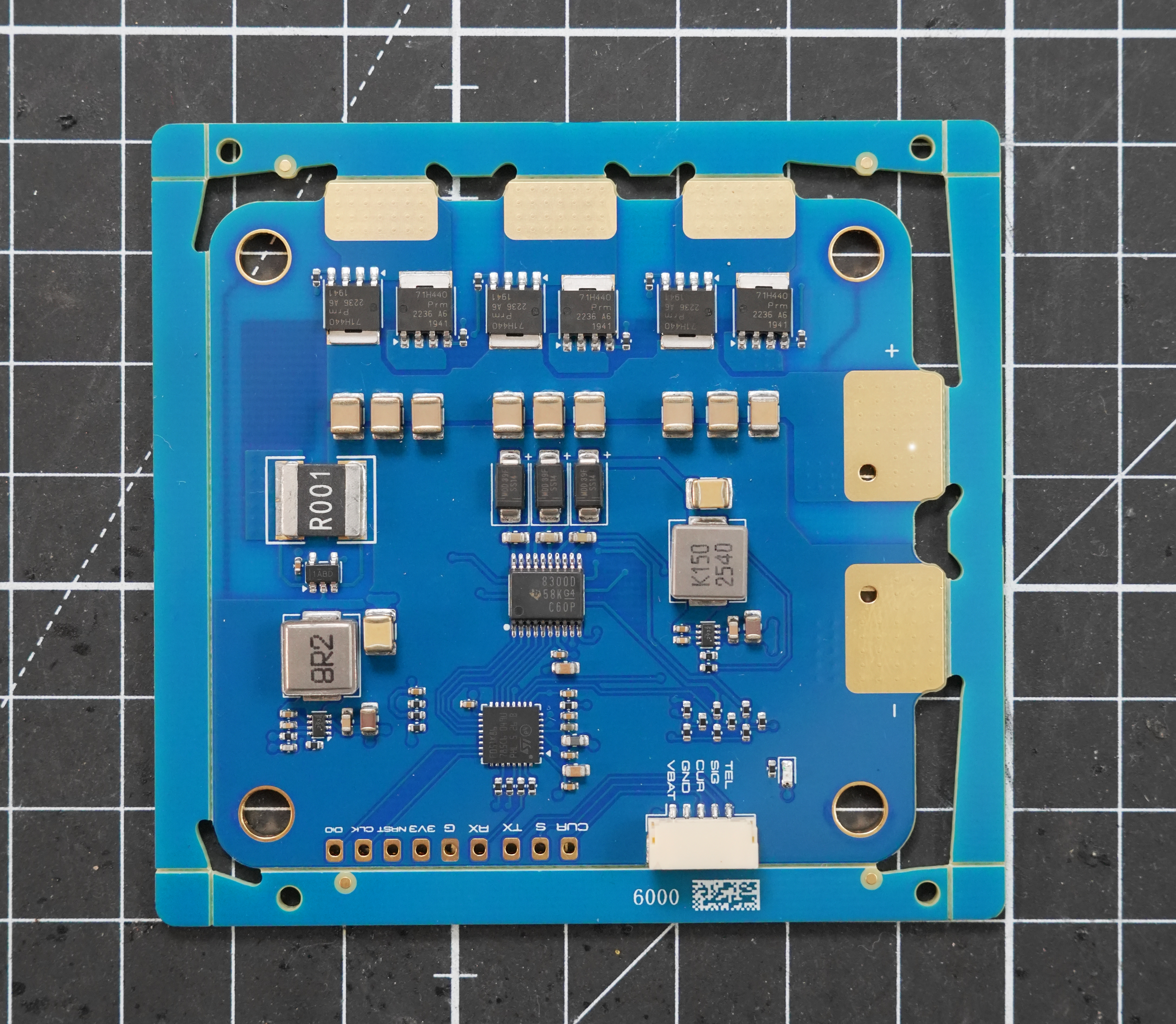
An open-source closed loop ESC PCB / Hardware platform. Based on a STM32F051 (Cortex M0 based) MCU. Tested using AM32 ESC software.
81 parts8

 10x-Aero/ESC-Development-Board77
A 6S AM32-compatible ESC built as a proof of concept for learning how to design an ESC from scratch
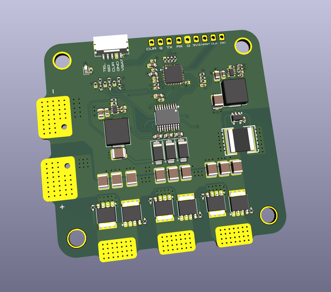
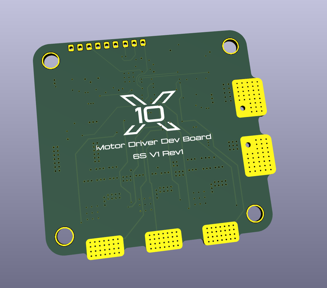
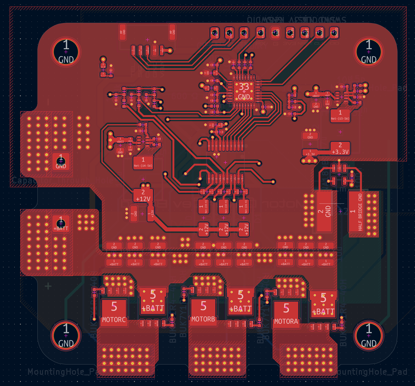
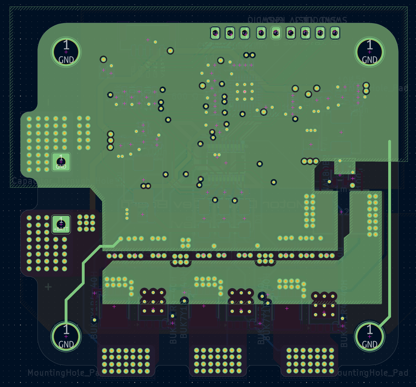
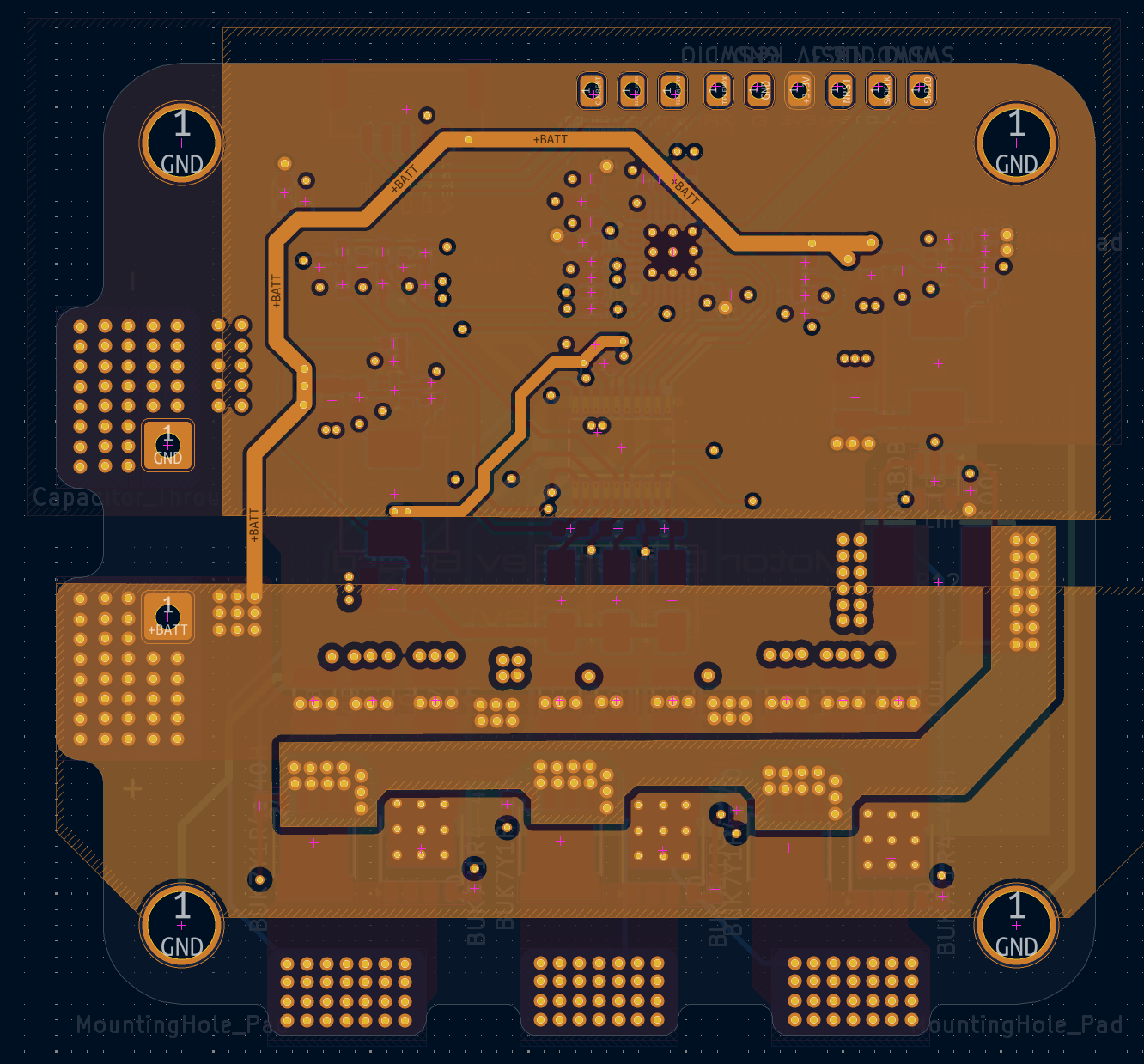
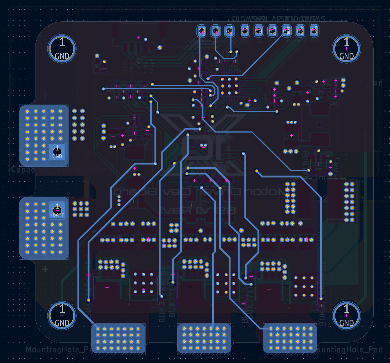
10X ESC V1 is an open-source printed circuit board by 10x-Aero, from the 10x-Aero/ESC-Development-Board repository on GitHub. It is a 4-layer board of 66 × 61.8 mm with 98 parts on 69 nets, routed with 482 tracks and 416 vias.
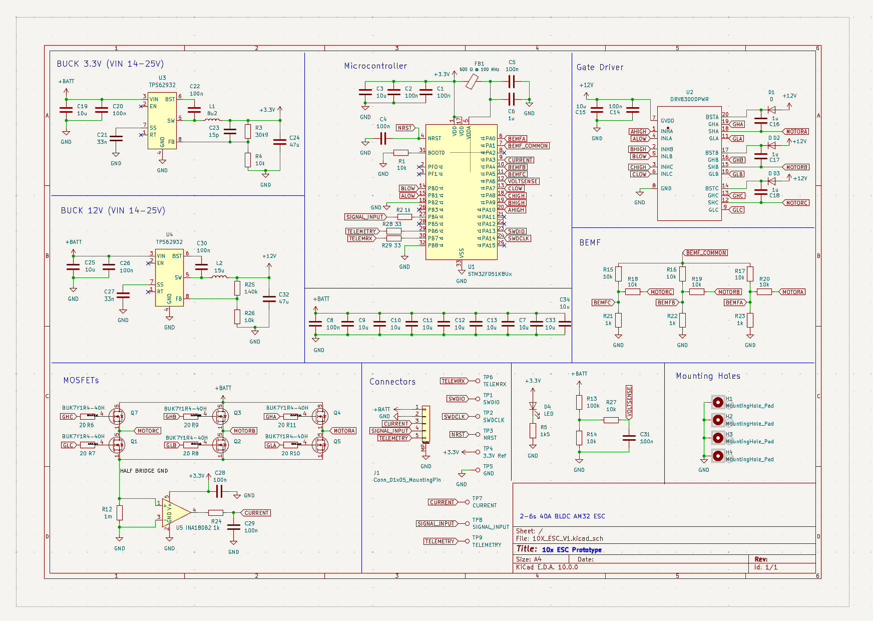
It is built around the TPS62932DRL, DRV8300DPWR-MS and BUK7Y1R4-40H. Its parts include 34 capacitors, 29 resistors, 6 transistors, 5 ICs and 4 diodes. It belongs with the robots and motor control boards and the STM32 boards of this library.
https://github.com/user-attachments/assets/5f652ef7-dc9c-4700-bebd-08a81333550c
A 6S AM32-compatible ESC built as a proof of concept for learning how to design an ESC from scratch. It gets a motor spinning — that's about the extent of what's guaranteed. Beyond that, expect rough edges.
The design is sloppy in places. If you spot schematic, layout, or component choices that actively work against basic ESC functionality, open an issue.
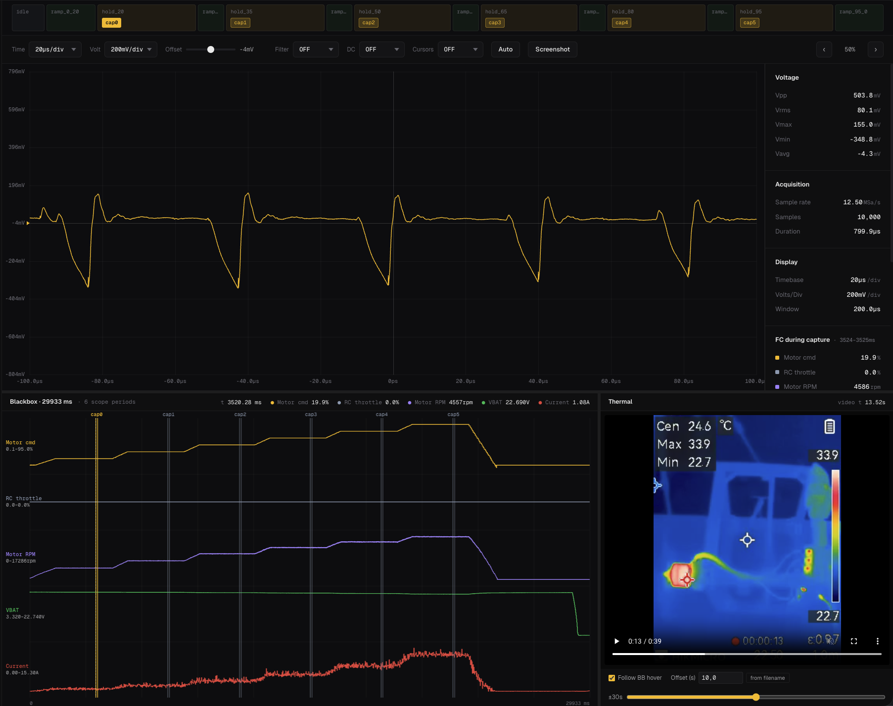
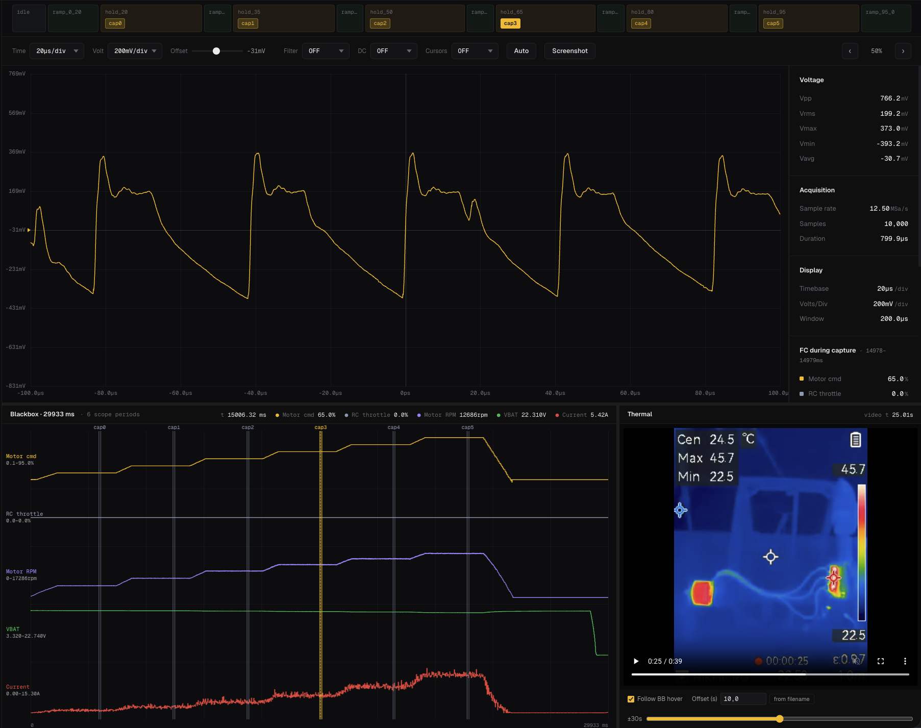
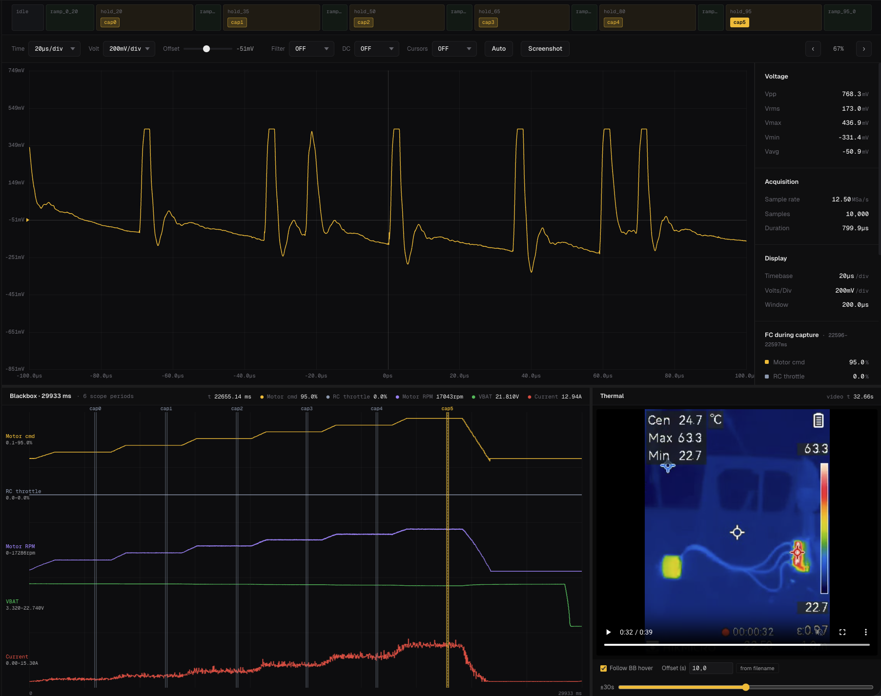
| t (s) | Action | Throttle | Duration |
|---|---|---|---|
| 0.0 | Idle | — | 1.0 s |
| 1.0 | Ramp | 0 → 20% | 1.5 s |
| 2.5 | Hold (capture) | 20% | 2.0 s |
| 4.5 | Ramp | 20 → 35% | 0.8 s |
| 5.3 | Hold (capture) | 35% | 2.0 s |
| 7.3 | Ramp | 35 → 50% | 0.8 s |
| 8.1 | Hold (capture) | 50% | 2.0 s |
| 10.1 | Ramp | 50 → 65% | 0.8 s |
| 10.9 | Hold (capture) | 65% | 2.0 s |
| 12.9 | Ramp | 65 → 80% | 0.8 s |
| 13.7 | Hold (capture) | 80% | 2.0 s |
| 15.7 | Ramp | 80 → 95% | 0.8 s |
| 16.5 | Hold (capture) | 95% | 2.0 s |
| 18.5 | Ramp down | 95 → 0% | 1.5 s |
| 20.0 | End | — | — |
https://github.com/user-attachments/assets/3ce99b9d-343a-43b4-ace9-065e4792fe87
General workflow for getting AM32 running on any custom STM32-based ESC, not just this one. Two things to figure out for your own board: which AM32 target matches your pin layout, and how to physically flash it.
AM32 organizes pin assignments in two layers:
F0_A, F0_B, etc.) and listed in the AM32 Supported Hardware wiki.Inc/targets.h in the am32-firmware/AM32 repo as #ifdef blocks.Compare your schematic against the hardware group table. If one matches your phase outputs, BEMF pins, and signal input exactly, use it and write a target that points to your ADC pins. If nothing matches, you'll need to define a new hardware group — that means editing the MCU-level source, not just a target header.
Match your signal input pin carefully. The bootloader .hex filename encodes which pin it expects (e.g. ..._PB4_V17.hex expects the signal on PB4). Mismatches mean the ESC won't respond to the configurator.
SWD only — the bootloader has to go on over ST-Link. Wire SWDIO, SWCLK, and GND from the ST-Link to the SWD pads on the ESC, and power the ESC from a LiPo.
.hex to 0x08000000.Once the bootloader is on, the main firmware goes over the signal wire via FC passthrough — no more SWD needed.
.hex matching your target from the AM32 releases..hex.The FC needs to be running a DShot protocol (300 or 600) for passthrough to work, and the ESC needs battery power — USB alone won't boot it.
| Qty | Value | Footprint | References |
|---|---|---|---|
| 11 | 10k | Resistor_SMD:R_0402_1005Metric | R1, R4, R14, R15, R16, R17, R18, R19, R20, R26, R27 |
| 10 | 100n | Capacitor_SMD:C_0402_1005Metric | C1, C2, C4, C5, C14, C22, C28, C29, C30, C31 |
| 8 | 10u | Capacitor_SMD:C_1210_3225Metric | C7, C9, C10, C11, C12, C13, C33, C34 |
| 6 | 20 | Resistor_SMD:R_0402_1005Metric | R6, R7, R8, R9, R10, R11 |
| 6 | BUK7Y1R4-40H | Package_TO_SOT_SMD:LFPAK56 | Q1, Q2, Q3, Q4, Q5, Q7 |
| 5 | 1k | Resistor_SMD:R_0402_1005Metric | R2, R21, R22, R23, R24 |
| 4 | MountingHole_Pad | Footprints:Flightcontroller_MountingHolePad_M4 | H1, H2, H3, H4 |
| 3 | 1u | Capacitor_SMD:C_0603_1608Metric | C16, C17, C18 |
| 3 | D | Diode_SMD:D_SMA | D1, D2, D3 |
| 2 | 100n | Capacitor_SMD:C_0603_1608Metric | C20, C26 |
| 2 | 10u | Capacitor_SMD:C_0603_1608Metric | C3, C15 |
| 2 | 10u | Capacitor_SMD:C_0805_2012Metric | C19, C25 |
| 2 | 33 | Resistor_SMD:R_0402_1005Metric | R28, R29 |
| 2 | 33n | Capacitor_SMD:C_0402_1005Metric | C21, C27 |
| 2 | 47u | Capacitor_SMD:C_1210_3225Metric | C24, C32 |
| 2 | SWDIO | Footprints:Flightcontroller_Solder_Pad | TP1, TP6 |
| 2 | TPS62932 | Package_TO_SOT_SMD:SOT-583-8 | U3, U4 |
| 1 | |||
| 1 | 100k | Resistor_SMD:R_0402_1005Metric | R13 |
| 1 | 100n | Capacitor_SMD:C_1210_3225Metric | C8 |
| 1 | 140k | Resistor_SMD:R_0402_1005Metric | R25 |
| 1 | 15p | Capacitor_SMD:C_0402_1005Metric | C23 |
| 1 | 15u | Inductor_SMD:L_KOHERelec_MDA7030 | L2 |
| 1 | 1k5 | Resistor_SMD:R_0402_1005Metric | R5 |
| 1 | 1m | Footprints:R2725 | R12 |
| 1 | 1u | Capacitor_SMD:C_0402_1005Metric | C6 |
| 1 | 3.3V Ref | Footprints:Flightcontroller_Solder_Pad | TP4 |
| 1 | 30k9 | Resistor_SMD:R_0402_1005Metric | R3 |
| 1 | 600 Ω @ 100 MHz | Inductor_SMD:L_0603_1608Metric | FB1 |
| 1 | 8u2 | Inductor_SMD:L_KOHERelec_MDA7030 | L1 |
| 1 | CURRENT | Footprints:Flightcontroller_Solder_Pad | TP7 |
| 1 | Conn_01x05_MountingPin | Connector_JST:JST_GH_SM05B-GHS-TB_1x05-1MP_P1.25mm_Horizontal | J1 |
| 1 | DRV8300DPWR | Footprints:TSSOP-20_L6.5-W4.4-P0.65-LS6.4-BL | U2 |
| 1 | GND | Footprints:Flightcontroller_Solder_Pad | TP5 |
| 1 | INA180B2 | Package_TO_SOT_SMD:SOT-23-5 | U5 |
| 1 | LED | LED_SMD:LED_0603_1608Metric | D4 |
| 1 | LOGO | LOGO | G*** |
| 1 | NRST | Footprints:Flightcontroller_Solder_Pad | TP3 |
| 1 | SIGNAL_INPUT | Footprints:Flightcontroller_Solder_Pad | TP8 |
| 1 | STM32F051K8Ux | Package_DFN_QFN:QFN-32-1EP_5x5mm_P0.5mm_EP3.45x3.45mm | U1 |
| 1 | SWDCLK | Footprints:Flightcontroller_Solder_Pad | TP2 |
| 1 | TELEMETRY | Footprints:Flightcontroller_Solder_Pad | TP9 |
The 97 most common of 98 parts.
0BAB1/HOLY_ESC
An open-source closed loop ESC PCB / Hardware platform. Based on a STM32F051 (Cortex M0 based) MCU. Tested using AM32 ESC software.


RobertGawron/GammaSpectrometer
Device for quantitative analyze energy spectra of gamma-ray sources. Allows to study what radioactive isotopes in what quantities are present in measured sample.

mschwingen/hardware
Hardware designs by Michael Schwingen, michael at schwingen dot org

peterisza/iec62386-wall-panel
Wall panel for smart homes. 2 wires, no polarity, arbitrary bus topology, exchangeable front panel with hardware capacitive buttons, temperature+humidity+pressure+CO2.


jussty/ncv7240-driver
KiCad 8 PCB: 4x NCV7240 octal low-side drivers + ESP32-S3 + AP33772S USB-C PD EPR (24V)

manhoosbilli1/smart-peltier-driver-esp32-v1
Smart Peltier driver, ESP32 (v1 - v2 in active development)
It measures 66 × 61.8 mm and has 4 copper layers, 1.6 mm thick.
98 parts, built around the TPS62932DRL, DRV8300DPWR-MS and BUK7Y1R4-40H. The full list of its parts is on this page, with links to each part's symbol and footprint where PCBKit's library has them.
From the 10x-Aero/ESC-Development-Board repository on GitHub, at the commit this page was made from: the board is 10X_ESC_V1.kicad_pcb and its schematic 10X_ESC_V1.kicad_sch. PCBKit opens the board in the browser, with nothing to install.
Its repository states no licence, so its author keeps all rights: ask 10x-Aero before reusing the design.