Skip to the content
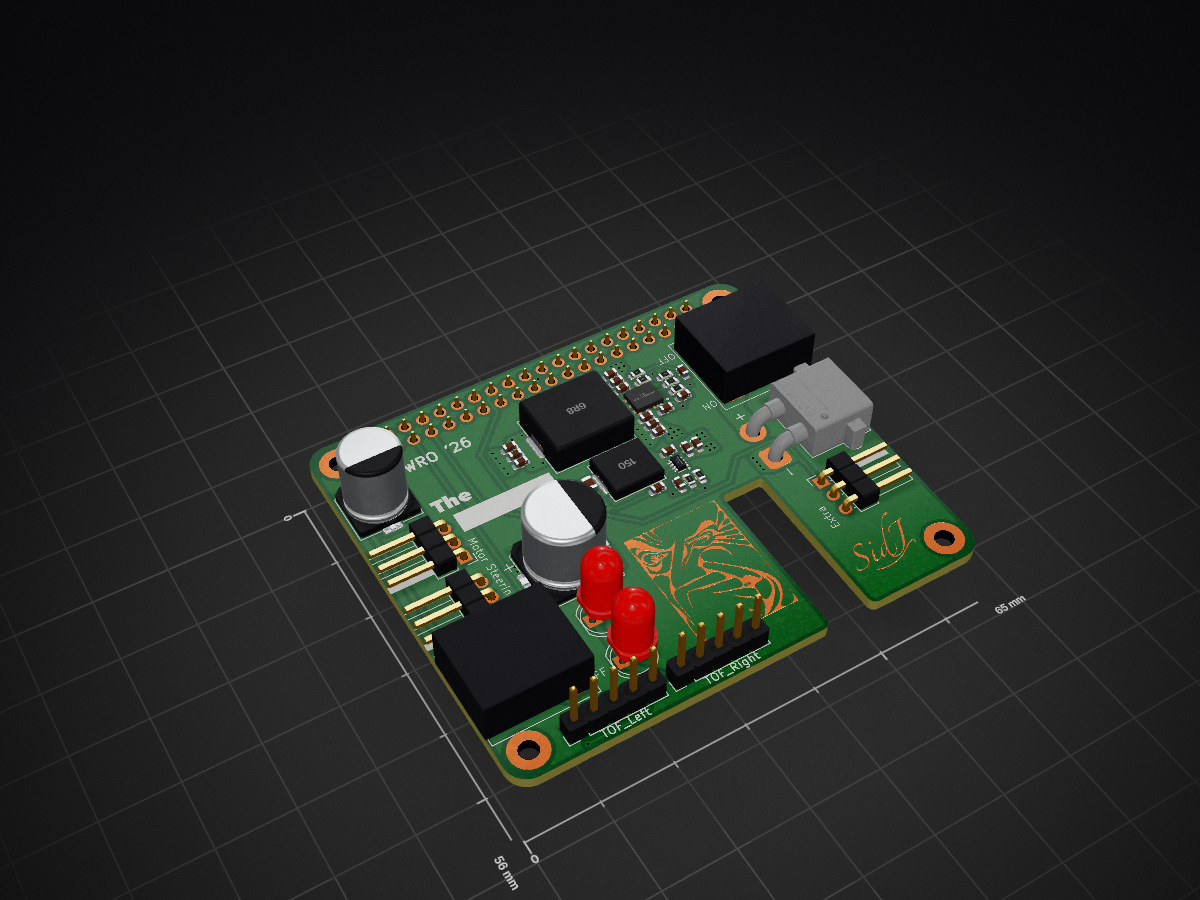
4 layers65 × 56 mm2026 WRO Hat, the printed circuit board in 3D
Size
65 × 56 mm
Copper layers
4
Thickness
1.6 mm
Parts
49
Nets
48
Pads
165
Tracks, vias
180, 102
Pours
27
Routed
Yes
KiCad
KiCad 10.0 (file 20260206)
Created
23 Jun 2026
Updated
26 Aug 2026

Overview

2026 WRO Hat is an open-source printed circuit board by Spaceflakes, from the Spaceflakes/2026-FE-The-Rdacted repository on GitHub. It is a 4-layer board of 65 × 56 mm with 49 parts on 48 nets, routed with 180 tracks and 102 vias.

It is built around the LM61460AFSQRJRRQ1 and TPS62932DRL. Its parts include 20 capacitors, 7 resistors, 4 connectors, 2 ICs and 2 diodes.

Main components

2

README

README.md

WRO-2026

The Redacted

logo

The official repository of The Redacted for WRO - Future Engineers 2026

Content

Folders

  • Engineering Manual: Official manual of team The Redacted for WRO FE 26 (manual.pdf). Contains component selection, CAD, PCB schematics, and assembly guides.
  • PCBA: Complete set of KiCad PCB files, manufacturing outputs (Gerbers), interactive HTML BOM, and documentation.
  • t-photos: Team photos (1 formal, 2 informal).
  • v-photos: 6 photos of the vehicle (front, back, left, right, top, bottom).
  • video: video.md file with the official vehicle demonstration video link.
  • schemes: Schematic diagrams, motor connections, power distribution, and 3D PCB renders.
  • src: ROS 2 control software nodes (motion, LiDAR, camera/vision, parking logic).
  • models: 3D CAD model files (STEP format).

Index


The Redacted

Members

  1. Anvay Jain
    Grade 9, The Sanskaar Valley School. Head of this repository. Interested in Space, Science, KSP, and Mathematics.
  2. Siddesh Jain
    12th Grader, Billabong High International School. Lead engineer/development head. CAD, hardware, system architecture.
  3. Prayash
    Co-engineer and robotics developer. Software integration, testing, and mechanical assembly.

Team Pictures

Formal

Formal Team Photo

Informal

Informal Team Photo 1
Informal Team Photo 2


Vehicle Photos and Video

Photos

Vehicle photographs showing all 6 sides are available in the /v-photos folder.

Videos

The demonstration video link and operational breakdown are located in /video/video.md.


Hardware Materials

NameLink
Rpi 4B/5Link
LiDARLink
ServoLink
WheelsLink
Pi CameraLink
Custom 2026 WRO Hat PCBLink
ESC + MotorLink
Battery2x DOGCOM 4S 850 mAh 150C LiPo
GearsCustom 3D Printed Bevel Gears
PCB ComponentsTI LM61460 (5.15V @ 6A) & TPS62932 (8V @ 2A)
Carbon Fiber Stock12mm OD x 10mm ID Tubes & 3mm OD Rods

PCB Design & Prototype PCB

Prototype PCB
  • Issue: Standard 5.0V buck converters caused under-voltage warnings on the Pi 4B under load.
  • Solution: Designed 2026 WRO Hat for a stabilized 5.15V rail at 6A using the TI LM61460.
  • LC Hot-Plug Fix: Added a 1000 µF electrolytic capacitor between switch output and GND to dissipate inrush energy and prevent voltage ringing.
PCB Design
  • 4-Layer Stackup:
    • Layer 1: High-speed switching/control.
    • Layer 2: Ground plane.
    • Layer 3: Power planes (BATT, 5.15V, 8.0V).
    • Layer 4: Ground plane and secondary signals.

Mobility Management

  • Drive System: Surpass Hobby 3674 1700KV brushless motor + 120A 4S ESC.
  • Differential Gearbox: 3D-printed, 2:7 gear reduction ratio.
  • Steering: Direct-drive Ackerman system with S2500M 25 kg-cm servo on 8V rail.
  • Bearing/Axle Support: Needle roller/thrust bearings for front knuckles; carbon fiber tubes for rear axles.

Design

  • Wheelbase: 184.3 mm.
  • Width: <180 mm.
  • Height: <80 mm.
  • Chassis: Carbon fiber rods for structural rigidity.

Power Management and Sense Management

Power Management

  • Battery: 2x DOGCOM 4S 850 mAh LiPo in parallel (1700 mAh total).
  • 5.15V Rail: TI LM61460 (6A) for RPi 4B and LiDAR.
  • 8.0V Rail: TI TPS62932 (2A) for steering servo.

Sense Management

  • YD-LiDAR X4 Pro: 360° 2D Laser Range Finder for mapping/navigation.
  • Arducam IMX219: 175° FOV camera for pillar color classification.

Schematic Diagram

  • Power Input: XT30 connector (14.8V–16.8V).
  • Interfaces: RPi 4B GPIO, USB (LiDAR), CSI (Camera), Expansion Ports (ToF sensors).

Obstacle Management

Strategy

Uses ROS 2 for modularity, combining LiDAR for 3D mapping and Camera for 2D pillar color classification.

Logic

  • Round 1 (Open): Wall-following via LiDAR and lane maintenance.
  • Round 2 (Obstacle): Pillar detection -> Camera classification -> Dynamic path planning.
  • Parking: Automated sequence using LiDAR/Camera boundary detection and PID feedback.

Our Journal

  • June: Strategy, sensing evaluation, concept sketches.
  • July: CAD modeling, PCB design, tire molding, printing.
  • August: Assembly, PCB reflow, ROS 2 software development, documentation.

The journal is one of the most detailed description and accounts for all the decision made. It should most definitely be read.


Gantt Chart

Task / MilestoneJuneJulyAugust
Concept & SelectionX
3D CAD ModelingX
KiCad PCB DesignX
SLA Tire MoldsX
3D Print & AssemblyXX
PCB & ReflowX
ROS 2 SoftwareX
Integration & TestingX

Parts

49
QtyValueFootprintReferences
44.7uCapacitor_SMD:C_0603_1608MetricC1, C2, C3, C4
4MountingHoleMountingHole:MountingHole_2.5mm_Pad_TopBottomH1, H2, H3, H4
3100nCapacitor_SMD:C_0603_1608MetricC12, C14, C16
347uCapacitor_SMD:C_0603_1608MetricC5, C6, C7
2100kResistor_SMD:R_0603_1608MetricR2, R5
2220nCapacitor_SMD:C_0603_1608MetricC8, C9
2LEDLED_THT:LED_D5.0mmD1, D2
110kResistor_SMD:R_0603_1608MetricR7
110uCapacitor_SMD:C_0603_1608MetricC13
112pCapacitor_SMD:C_0603_1608MetricC17
115uInductor_SMD:L_Chilisin_BMRB00060618L2
11kResistor_SMD:R_0603_1608MetricR3
11pCapacitor_SMD:C_0603_1608MetricC11
11uCapacitor_SMD:C_0603_1608MetricC10
1220uCapacitor_SMD:CP_Elec_8x10C19
124.3kResistor_SMD:R_0603_1608MetricR4
1270uCapacitor_SMD:CP_Elec_10x10C20
132.4kResistor_SMD:R_0603_1608MetricR1
133nCapacitor_SMD:C_0603_1608MetricC15
147uCapacitor_SMD:C_0805_2012Metric_Pad1.18x1.45mm_HandSolderC18
16.8uInductor_SMD:L_Chilisin_BMRF00101040L1
190.9kResistor_SMD:R_0603_1608MetricR6
1ExtraConnector_PinHeader_2.54mm:PinHeader_1x03_P2.54mm_HorizontalM3
1LM61460AFSQRJRRQ1TI:IC_LM61460AFSQRJRRQ1U1
1LOGOmy lib:SignG***
1POWERmy lib:SwitchSW1
1Programmy lib:SwitchSW2
1Raspberry_Pi_4Connector_PinSocket_2.54mm:PinSocket_2x20_P2.54mm_VerticalJ1
1SteeringConnector_PinHeader_2.54mm:PinHeader_1x03_P2.54mm_HorizontalM2
1TOF_LeftConnector_PinHeader_2.54mm:PinHeader_1x05_P2.54mm_VerticalJ4
1TOF_RightConnector_PinHeader_2.54mm:PinHeader_1x05_P2.54mm_VerticalJ3
1TPS62932Package_TO_SOT_SMD:SOT-583-8U2
1ThrottleConnector_PinHeader_2.54mm:PinHeader_1x03_P2.54mm_HorizontalM1
1XT30_PowerConnector_AMASS:AMASS_XT30PW-M_1x02_P2.50mm_HorizontalJ2

The 47 most common of 49 parts.

Similar boards

  • 4 layers164.9 × 102 mmCarrier, the printed circuit board in 3D

    Carrier

    AJXD2/carplay-project

    One board that turns the Pi 4 + 7" screen into a complete car radio replacement. It bolts onto the Pi like a HAT, plugs into the truck's radio harness, and does everything the factory radio did plus what the Pi needs:

    171 parts
  • 4 layers66 × 61.8 mm10X ESC V1, the printed circuit board in 3D

    10X ESC V1

    10x-Aero/ESC-Development-Board

    A 6S AM32-compatible ESC built as a proof of concept for learning how to design an ESC from scratch

    98 parts77
  • 4 layers54.7 × 75.8 mmEsphome dot, the printed circuit board in 3D

    Esphome dot

    gcormier/esphome-dot

    Beginnings of a replacement PCB for Amazon Echo Dot v5.

    62 parts16
  • 4 layers100 × 100 mmGammaSpectrometer, the printed circuit board in 3D

    GammaSpectrometer

    RobertGawron/GammaSpectrometer

    Device for quantitative analyze energy spectra of gamma-ray sources. Allows to study what radioactive isotopes in what quantities are present in measured sample.

    326 parts16MIT
  • 2 layers85 × 56 mmYoga v2, the printed circuit board in 3D

    Yoga v2

    mschwingen/hardware

    Hardware designs by Michael Schwingen, michael at schwingen dot org

    85 parts10
  • 4 layers64.9 × 39.2 mmHOLY ESC, the printed circuit board in 3D

    HOLY ESC

    0BAB1/HOLY_ESC

    An open-source closed loop ESC PCB / Hardware platform. Based on a STM32F051 (Cortex M0 based) MCU. Tested using AM32 ESC software.

    81 parts8
  • 2 layers43 × 43 mmIec62386-panel, the printed circuit board in 3D

    Iec62386-panel

    peterisza/iec62386-wall-panel

    Wall panel for smart homes. 2 wires, no polarity, arbitrary bus topology, exchangeable front panel with hardware capacitive buttons, temperature+humidity+pressure+CO2.

    64 parts2
  • 4 layers200 × 120 mmNcv7240-driver, the printed circuit board in 3D

    Ncv7240-driver

    jussty/ncv7240-driver

    KiCad 8 PCB: 4x NCV7240 octal low-side drivers + ESP32-S3 + AP33772S USB-C PD EPR (24V)

    72 parts

Questions

How big is the 2026 WRO Hat PCB?

It measures 65 × 56 mm and has 4 copper layers, 1.6 mm thick.

What parts does the 2026 WRO Hat use?

49 parts, built around the LM61460AFSQRJRRQ1 and TPS62932DRL. The full list of its parts is on this page, with links to each part's symbol and footprint where PCBKit's library has them.

Where can I download the 2026 WRO Hat KiCad files?

From the Spaceflakes/2026-FE-The-Rdacted repository on GitHub, at the commit this page was made from: the board is PCBA/Kicad/2026 WRO Hat.kicad_pcb and its schematic PCBA/Kicad/2026 WRO Hat.kicad_sch. PCBKit opens the board in the browser, with nothing to install.

Can I use the 2026 WRO Hat design in my own project?

Its repository states no licence, so its author keeps all rights: ask Spaceflakes before reusing the design.