
2 layers189.5 × 204.9 mm
SmartSpin2k Panelized
doudar/SmartSpin2k
Transform your spin bike into a Smart Trainer!
749 parts292GPL-2.0

 0x007E/u3a_rs232
RS232-Adapter module for U3A
U3a rs232 is an open-source printed circuit board by 0x007E, from the 0x007E/u3a_rs232 repository on GitHub. It is a 2-layer board of 34.5 × 26.4 mm with 16 parts on 28 nets, routed with 64 tracks and 17 vias.
It is built around the MAX3232ID. Its parts include 6 capacitors, 3 connectors and 1 IC. It belongs with the interfaces and adapters and radio and wireless boards of this library.


U3A_rs232 - RS232 - Adapter for U3A
The U3A_rs232 project is based on a (MAX3232) that ist used to change the TTL/CMOS level to the required level of TIA/EIA-232-F standard. It can simply be adapted to the U3A-Module. The Module can be used with a DSUB connector.
To use it with a DSUB connector it is necessary to create a connector cable that can be plugged into the IDC connector.
| Experience | Level |
|---|---|
| Soldering | |
| Mechanical |
| Type | File | Description |
|---|---|---|
| Schematic | pdf / cadlab | Schematic files |
| Board | pdf / cadlab | Board file |
| Drill | Drill file | |
| BoM | xlsx / html | Bill of Material as Excel/interactive HTML |
| PCB | zip / tar | KiCAD/Gerber/BoM/Drill files |
| Mechanical | zip / tar | FreeCAD/Housing and PCB (STEP/STL) files |
There are two parts of the hardware. The pcb and the housing of the U3A_rs232. The pcb is created with KiCAD and the housing with FreeCAD. All files are built with github actions so that they are ready for a production environment. The housing is printed with a 3D-printer (Dremel 3D40).
The circuit board is populated on both sides (Top, Bottom). The best way for soldering the SMD components is within a vapor phase soldering system and for the THT components with a standard soldering system.


The housing has a tolerance of 0.2mm on each side of the case. So the pcb should fit perfectly in the housing. The tolerance can be modified with FreeCAD in the Parameter Spreadsheet.
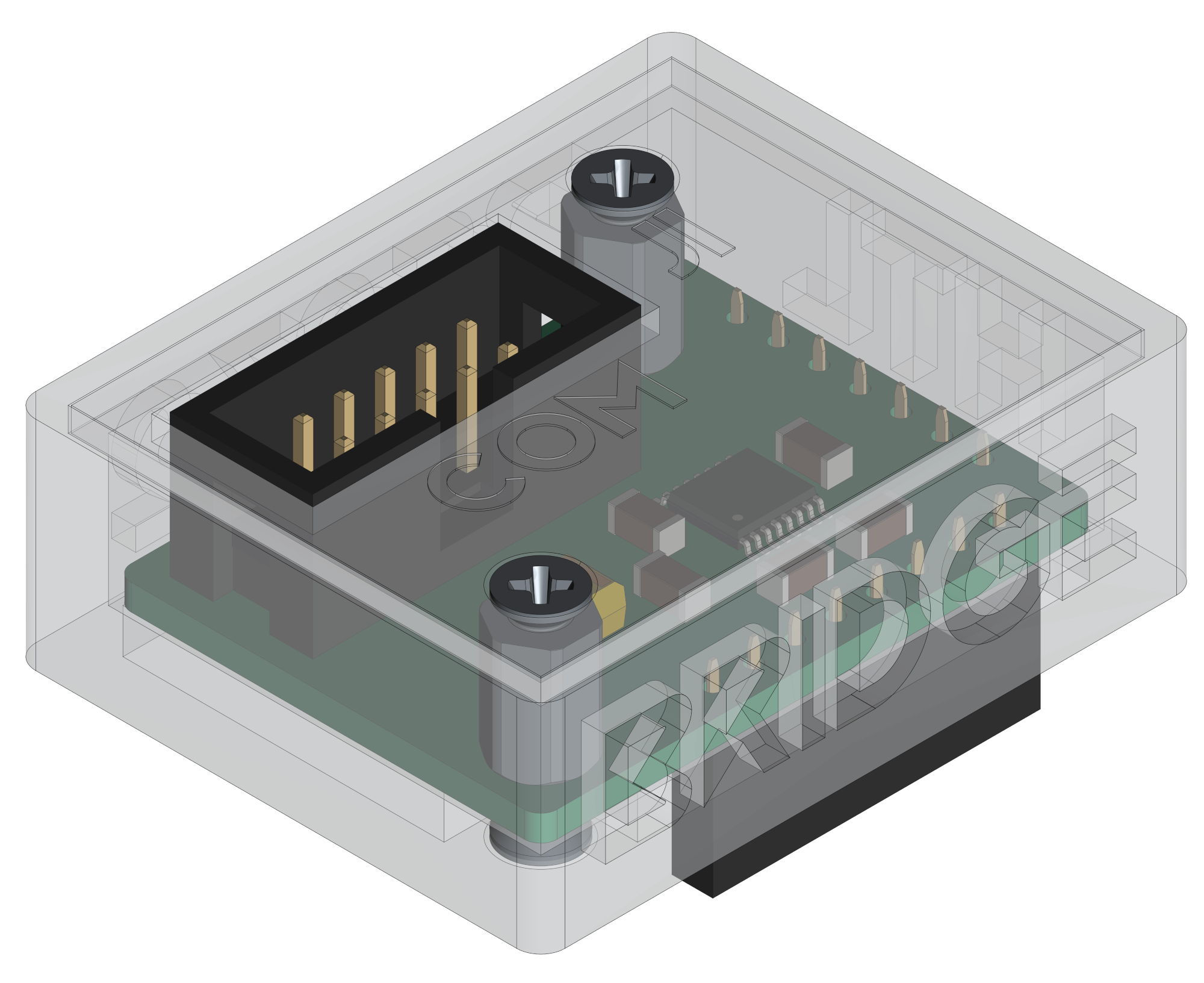
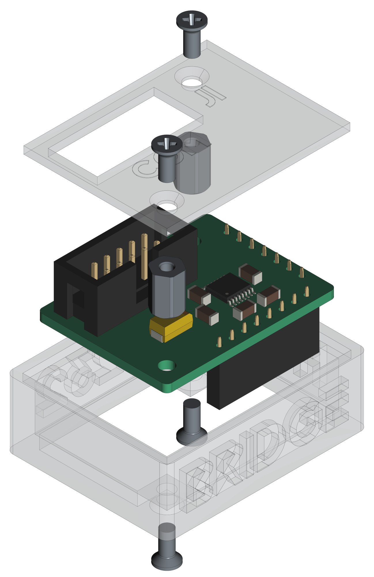
The U3A_rs232 is powerd over the U3A board with 5V. The voltage of the pins are driven by a MAX3232 that creates its own voltage for data transmission that meets the TIA/EIA-232-F standard.
#
#            +--------------------------------+           +-----------------------------------+      +---------------------+
#            |                              J2|           |J2     U                       +---+---+  |                     |
#            | J1         U3A_rs232        +--+--+     +--+--+    S                U      |  USB  |--+ +-----------------+ |
#         +--+--+                          | VCC +-----+ VCC |    B      UPDI      3      +---+---+  | | TeraTerm        | |
#         + GND | (5)                      | GND +-----+ GND |    /    +---+---+   A          |      | | ~~~~~~~~        | |
#         +-----+                          |  X  +-----| PDI |    U    |   |   |              |      | | ~~~~~           | |
#   L     + CTS | (8)                      | CTS +-----+ CTS |    A    |   |   |              |      | | ~~~~~~~~~~~~    | |
#   O     + RTS | (7)                      | RTS +-----+ RTS |    R    | X | X |              |      | |                 | |
#   O +---+ TXD | (3)                      | TXD +-----+ TXD |    T    +---+---+     +-+      |      | +-----------------+ |
#   P +---+ RXD | (2)                      | RXD +-----+ RXD |    /                 / /       |      |                     |
#   B     +--+--+                          +--+--+     +--+--+    U               +-+-+-+-+-+-+      | Computer            |
#   A        |                                |           |       P               | 5V  | 3V3 |      |                     |
#   C        |                                |           |       D               +-----+-----+      +---------------------+
#   K        |                                |           |       I         J4                |
#            |                                |           | +---+---+---+---+---+---+---+---+ |
#            |                                |           | | V | C | C | D | D | D | R | G | |
#            |                                |           +-+ C | B | B | C | T | C | I | N +-+
#            |                                |             | C | 3 | 2 | D | R | R |   | D |
# +--------------------------------+ +---+---+---+---+---+---+---+---+| Type | Link | Description |
|---|---|---|
| MAX3232 | UART / RS232 level converter | |
| KiCAD | web | KiCAD project page |
| FreeCAD | web | FreeCAD project page |
R. GAECHTER
| Qty | Value | Footprint | References |
|---|---|---|---|
| 3 | 470n | Capacitor_SMD:C_1206_3216Metric | C4, C5, C6 |
| 2 | 100n | Capacitor_SMD:C_1206_3216Metric | C2, C3 |
| 2 | MountingHole_Pad | MountingHole:MountingHole_2.7mm_M2.5_Pad | H1, H2 |
| 1 | 10u | Capacitor_Tantalum_SMD:CP_EIA-6032-28_Kemet-C | C1 |
| 1 | BIN | Symbol:WEEE-Logo_4.2x6mm_SilkScreen | FID3 |
| 1 | Conn_01x07_Socket | Connector_PinSocket_2.54mm:PinSocket_1x07_P2.54mm_Vertical | J2 |
| 1 | Conn_01x08_Socket | Connector_PinSocket_2.54mm:PinSocket_1x08_P2.54mm_Vertical | J4 |
| 1 | Conn_02x05_Odd_Even | Connector_IDC:IDC-Header_2x05_P2.54mm_Vertical | J1 |
| 1 | ESD | Symbol:ESD-Logo_6.6x6mm_SilkScreen | FID1 |
| 1 | MAX3232 | Package_SO:TSSOP-16_4.4x5mm_P0.65mm | U1 |
| 1 | OH | Symbol:OSHW-Logo_5.7x6mm_SilkScreen | FID2 |
| 1 | QR | Images:QR_0x007e | FID4 |
doudar/SmartSpin2k
Transform your spin bike into a Smart Trainer!


zephray/ELTerm
ANSI/VT100-compatible serial terminal built with Raspberry Pi Pico and EL640.480-AM/AG screen


Tjeerdie/SPECTRE
Speeduino compatible engine control unit (ECU) based around black STM32F407VET6 board.

scrapcomputing/ThrottleBlaster
A Turbo circuit with a MHz display that can slow down the CPU speed

cole8888/SRNE-Solar-Charge-Controller-Monitor
Read data from SRNE solar charge controllers.

It measures 34.5 × 26.4 mm and has 2 copper layers, 1.6 mm thick.
16 parts, built around the MAX3232ID. The full list of its parts is on this page, with links to each part's symbol and footprint where PCBKit's library has them.
From the 0x007E/u3a_rs232 repository on GitHub, at the commit this page was made from: the board is pcb/U3A_rs232.kicad_pcb and its schematic pcb/U3A_rs232.kicad_sch. PCBKit opens the board in the browser, with nothing to install.
Its repository states no licence, so its author keeps all rights: ask 0x007E before reusing the design.