
2 layers76.2 × 50.8 mm

 0x007E/rcl
Color Lamp
Rcl is an open-source printed circuit board by 0x007E, from the 0x007E/rcl repository on GitHub. It is a 2-layer board with 82 parts on 72 nets, routed with 219 tracks and 119 vias.
It is built around the ATTINY1604-SSF, FT230XS-R and AT24CM02-SSHM-T, with the MCP73833, AO3416A and BAT43 among its other parts. Its parts include 21 resistors, 20 capacitors, 15 diodes, 5 ICs and 3 connectors. It belongs with the lEDs and displays boards and the AVR (ATmega, ATtiny) boards of this library.


RCL - RGB Color Lamp
The RCL is a board with a set of APA102 or any other SPI controllable RGB-LED. The board itself is driven with 5V over USB and can be configured with the integrated UART interface (MCP2221A). The Color Lamp itself is controlled over the additional Touchpad (TPD) and can be switched on/off over a slide switch.
| Experience | Level |
|---|---|
| Soldering | |
| Mechanical |
| Type | File | Description |
|---|---|---|
| Schematic | pdf / cadlab | Schematic files |
| Board | pdf / cadlab | Board file |
| Drill | Drill file | |
| BoM | xlsx / html | Bill of Material as Excel/interactive HTML |
| PCB | zip / tar | KiCAD/Gerber/BoM/Drill files |
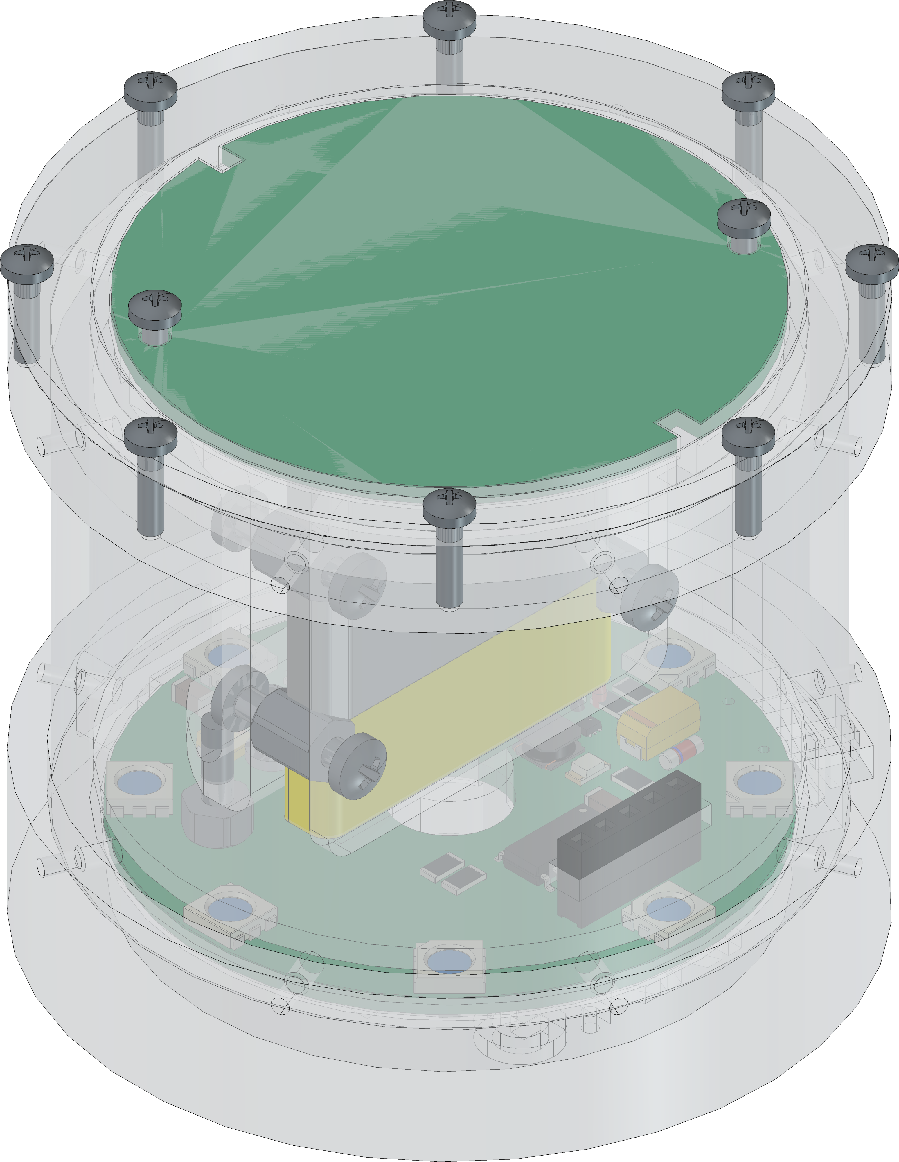
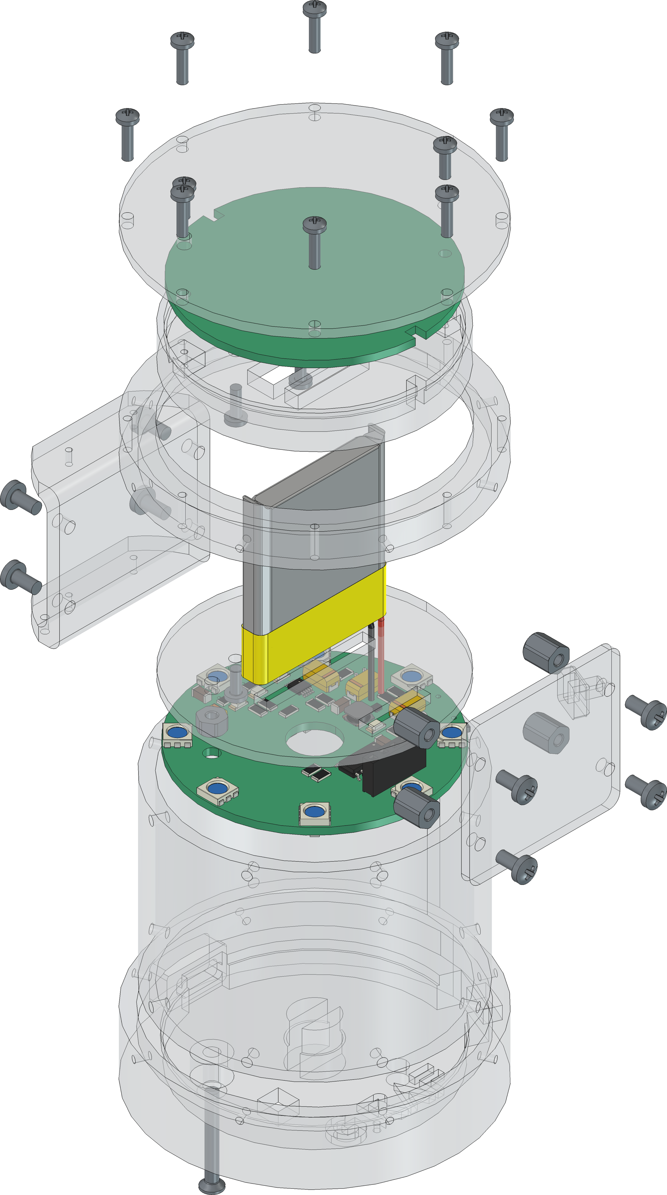
| Mechanical | zip / tar | FreeCAD/Housing and PCB (STEP/STL) files |
The pcb is created with KiCAD, the housing with FreeCAD. All files are built with github actions so that they are ready for a production environment.
The circuit board is populated on both sides (Top, Bottom). The best way for soldering the SMD components is within a vapor phase soldering system and for the THT components with a standard soldering system.


The housing has a tolerance of 0.2mm on each side of the case. So the pcb should fit perfectly in the housing. The tolerance can be modified with FreeCAD in the Parameter Spreadsheet.
| Type | Link | Description |
|---|---|---|
| APA102 | RGB Full Color LED | |
| T3A33BRG | Harvatek Surface Mount PLCC IC+RGB LEDs Data Sheet | |
| MCP2221A | USB 2.0 to I2C/UART Protocol Converter with GPIO |
R. GAECHTER
| Qty | Value | Footprint | References |
|---|---|---|---|
| 15 | 100n | Capacitor_SMD:C_1206_3216Metric | C2, C4, C7, C9, C10, C11, C12, C13, C14, C15, C16, C17, C18, C19, C20 |
| 8 | APA102 | LED_SMD:LED_RGB_5050-6 | D10, D11, D12, D13, D14, D15, D16, D17 |
| 4 | 10u | Capacitor_Tantalum_SMD:CP_EIA-6032-28_Kemet-C | C1, C5, C6, C8 |
| 4 | 1k | Resistor_SMD:R_1206_3216Metric | R4, R5, R6, R15 |
| 4 | 470 | Resistor_SMD:R_1206_3216Metric | R9, R16, R25, R26 |
| 4 | TestPoint_Probe | TestPoint:TestPoint_Pad_D1.0mm | TP1, TP2, TP3, TP4 |
| 3 | Red | LED_SMD:LED_1206_3216Metric | D3, D7, D9 |
| 2 | 0 | Resistor_SMD:R_0603_1608Metric | R21, R24 |
| 2 | 10k | Resistor_SMD:R_1206_3216Metric | R7, R18 |
| 2 | 22k | Resistor_SMD:R_1206_3216Metric | R20, R22 |
| 2 | 3k3 | Resistor_SMD:R_1206_3216Metric | R13, R14 |
| 2 | 5k1 | Resistor_SMD:R_1206_3216Metric | R1, R2 |
| 1 | 1.5A | Fuse:Fuse_1206_3216Metric | F2 |
| 1 | 100k | Resistor_SMD:R_1206_3216Metric | R8 |
| 1 | 10u | Capacitor_Tantalum_SMD:CP_EIA-3528-21_Kemet-B | C3 |
| 1 | 2.0A | Fuse:Fuse_1206_3216Metric | F1 |
| 1 | 2u2 | Inductor_SMD:L_Vishay_IFSC-1515AH_4x4x1.8mm | L1 |
| 1 | 330 | Resistor_SMD:R_1206_3216Metric | R27 |
| 1 | 70Ω/100Mhz/3A | Inductor_SMD:L_1206_3216Metric | FB1 |
| 1 | 732k | Resistor_SMD:R_1206_3216Metric | R3 |
| 1 | AO3416A | Package_TO_SOT_SMD:SOT-23 | Q4 |
| 1 | AT24CM02-SSHM | Package_SO:SOIC-8_3.9x4.9mm_P1.27mm | U3 |
| 1 | ATtiny1604-SS | Package_SO:SOIC-14_3.9x8.7mm_P1.27mm | U4 |
| 1 | BAT43 | Diode_SMD:D_MiniMELF | D6 |
| 1 | BIN | Symbol:WEEE-Logo_4.2x6mm_SilkScreen | FID2 |
| 1 | BSP613 | Package_TO_SOT_SMD:SOT-223 | Q1 |
| 1 | BZV55B5V6 | Diode_SMD:D_MiniMELF | D2 |
| 1 | Conn_01x02_Pin | Connector_JST:JST_PH_S2B-PH-K_1x02_P2.00mm_Horizontal | J2 |
| 1 | Conn_01x05_Pin | Connector_PinSocket_2.54mm:PinSocket_1x05_P2.54mm_Vertical | J3 |
| 1 | DO-214AC | Diode_SMD:D_SMA | D1 |
| 1 | ESD | Symbol:ESD-Logo_6.6x6mm_SilkScreen | FID4 |
| 1 | FT230XS | Package_SO:SSOP-16_3.9x4.9mm_P0.635mm | U5 |
| 1 | Green | LED_SMD:LED_1206_3216Metric | D8 |
| 1 | MCP73833 | Package_SO:MSOP-10_3x3mm_P0.5mm | U1 |
| 1 | MountingHole_Pad | MountingHole:MountingHole_3.2mm_M3_DIN965_Pad | H1 |
| 1 | OH | Symbol:OSHW-Logo2_7.3x6mm_SilkScreen | FID3 |
| 1 | QR | Images:QR_0x007e_very_small | FID1 |
| 1 | SW_DIP_x02 | Button_Switch_SMD:SW_DIP_SPSTx02_Slide_6.7x6.64mm_W8.61mm_P2.54mm_LowProfile | SW2 |
| 1 | SW_Push | Button_Switch_SMD:SW_SPST_PTS645 | SW3 |
| 1 | SW_SPDT | Button_Switch_SMD:SW_SPDT_CK_JS102011SAQN | SW1 |
| 1 | TPS61023DRLR | Package_TO_SOT_SMD:SOT-563 | U2 |
| 1 | USB_C_Receptacle | Connector_USB:USB_C_Receptacle_GCT_USB4110 | J1 |
82 parts, built around the ATTINY1604-SSF, FT230XS-R, AT24CM02-SSHM-T and MCP73833. The full list of its parts is on this page, with links to each part's symbol and footprint where PCBKit's library has them.
From the 0x007E/rcl repository on GitHub, at the commit this page was made from: the board is pcb/RCL.kicad_pcb and its schematic pcb/RCL.kicad_sch. PCBKit opens the board in the browser, with nothing to install.
Its repository states no licence, so its author keeps all rights: ask 0x007E before reusing the design.


