
2 layers

 0x007E/mad
Matrix Display
Mad is an open-source printed circuit board by 0x007E, from the 0x007E/mad repository on GitHub. It is a 2-layer board of 36 × 47 mm with 48 parts on 45 nets, routed with 130 tracks and 41 vias.
It is built around the AO3416A, BZV55B5V6 and TA20-11SRWA. Its parts include 12 transistors, 10 resistors, 4 capacitors, 3 diodes and 2 connectors. It belongs with the lEDs and displays boards and the AVR (ATmega, ATtiny) boards of this library.


MAD - Matrix Display
The MAD project is based on a pcb with an ATtiny406/ATtiny1606 and a Matrix LED Display. It can be used to display data sent over SPI or UART. The display also implements a small amount of characters from the ASCII table and also has internal space (EEPROM) for 16 special characters that can be programmed.
| Experience | Level |
|---|---|
| Soldering | |
| Mechanical | |
| Software |
| Type | File | Description |
|---|---|---|
| Schematic | pdf / cadlab | Schematic files |
| Board | pdf / cadlab | Board file |
| Drill | Drill file | |
| PCB | zip / tar | KiCAD/Gerber/BoM/Drill files |
| Mechanical | zip / tar | FreeCAD/Housing and PCB (STEP) files |
| Firmware | zip / tar | Firmware for ATtiny406/ATtiny1606 (Display) |
| Firmware (demo) | zip / tar | Test application(s) for ATmega16a |
There are two parts of the hardware. The pcb and the housing of the MAD. The pcb is created with KiCAD and the housing with FreeCAD. The software is programmed with Microchip (Atmel) Studio. All files are built with github actions so that they are ready for a production environment. The housing is printed with a 3D-printer (Dremel 3D40).
The circuit board is populated on both sides (Top, Bottom). The best way for soldering the SMD components is within a vapor phase soldering system and for the THT components with a standard soldering system.


The housing has a tolerance of 0.2mm on each side of the case. So the pcb should fit perfectly in the housing. The tolerance can be modified with FreeCAD in the Parameter Spreadsheet.
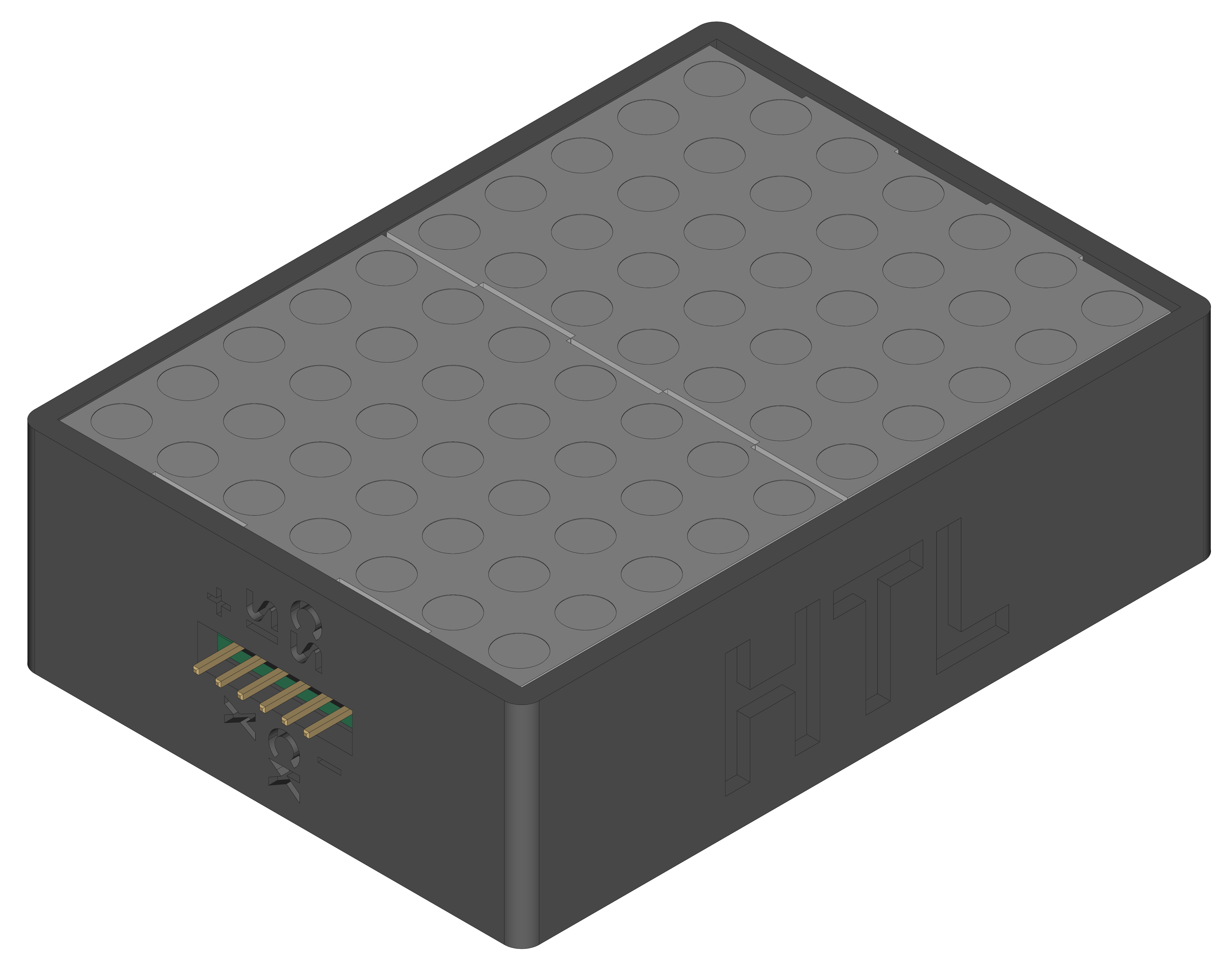
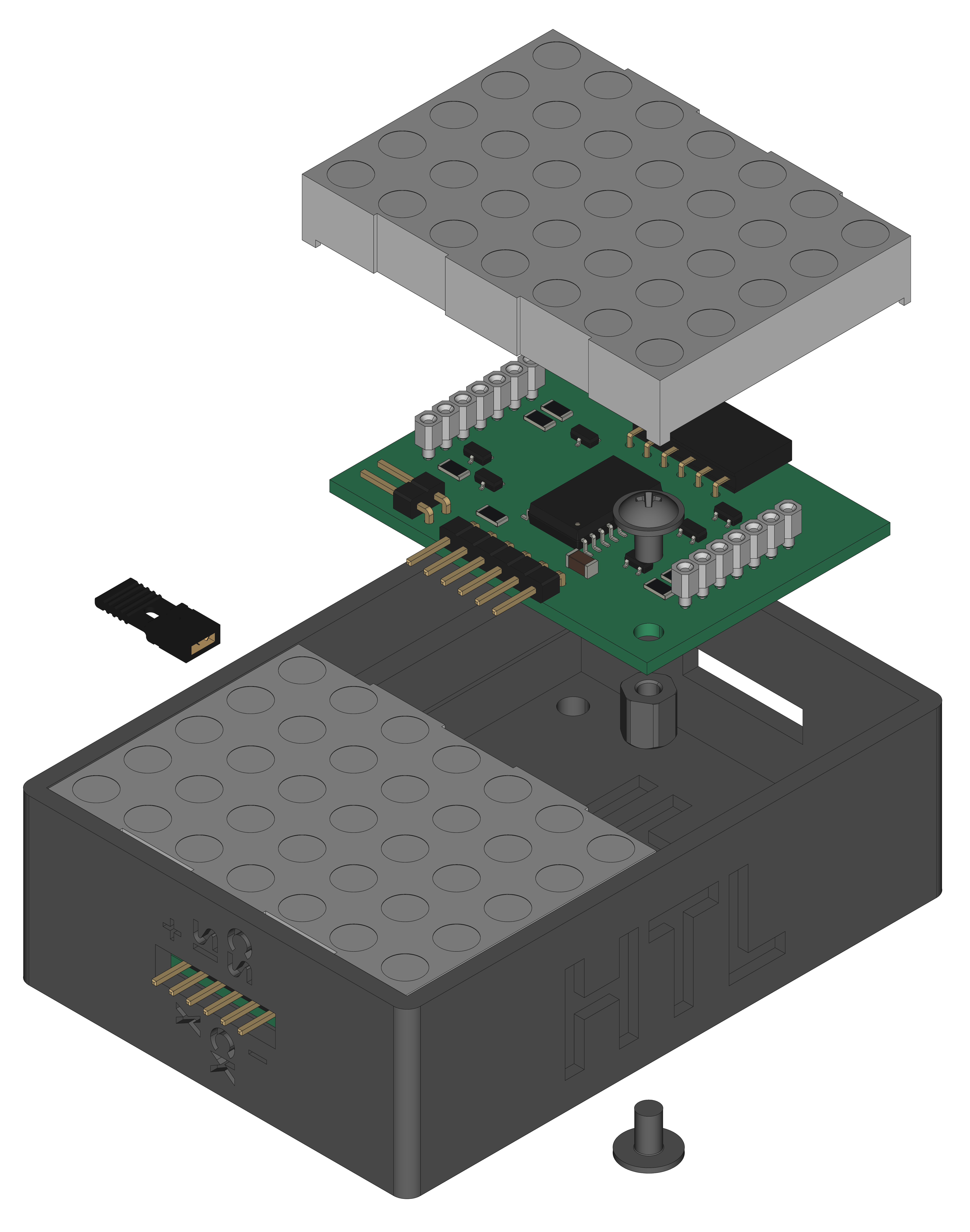
The MAD is powerd with 5V from an external source. With Jumper JP1 bridged the MAD can be programmed over UPDI. To enable UART mode the SS (CS) Pin must be held low (more details on the dataflow diagram) otherwise the SPI mode is enabled. In UART mode only one display can be driven. The SI pin gets TXDand the SO pin gets RXD. The firmware for the display can be downloaded (see the download section).
#         +-+                                         +----------+      +---------------------+
#        / /                                          |   U  +---+---+  |                     |
#      +-+-+-----------------+                        |   S  |  USB  |--+ +-----------------+ |
#      | JP1                 |                        |   B  +---+---+  | | AVR-Dude        | |
#      |    MAD - Display    |       +---------+      |   /      |      | | ~~~~~~~~        | |
#    +-+-+                 +-+-+   +-+-+  U    |      |   U      |      | | ~~~~~           | |
#    | 1 | VCC         VCC | 1 +---+VCC|  P  +-+-+  +-+-+ A      |      | | ~~~~~~~~~~~~    | |
#    | 2 | UPDI       UPDI | 2 +---+PDI|  D  |GND+--+GND| R      |      | |                 | |
#    | 3 | SI           SO | 3 |   +-+-+  I  |VCC+--+VCC| T      |      | +-----------------+ |
#    | 4 | SCK         SCK | 4 |     |       +---+  +---+ A      |      |                     |
#    | 5 | SS (CS)      SS | 5 +   +-+-+     |RxD+--+RxD| +------+      | Computer            |
#    | 6 | GND         GND | 6 +---+GND|     |TxD+--+TxD| |5V/3V3|      |                     |
#    +-+-+                 +-+-+   +-+-+     +-+-+  +-+-+ +------+      +---------------------+
#      +---------------------+       | ADAPTER |      +----+-----+
# +---------+| Register | Value |
|---|---|
WDTCFG | 0x00 |
BODCFG | 0x00 |
OSCCFG | 0x02 |
TCD0CFG | 0x00 |
SYSCFG0 | 0xF5 |
SYSCFG1 | 0x00 |
APPEND | 0x00 |
BOOTEND | 0x00 |
To setup
SW1asRESET(PA0) it is necessary to change theSYSCFG0-FUSE of theATtiny406/ATtiny1606. WARNING: To reset thePA0pin toUPDImode a12Vimpulse is necessary to program the FUSES again.
The display software can be controlled by SPI or UART. The interfaces are displayed in the dataflow diagram. There is a demo software to use the display directly over spi (MAD_Test) or a library (MAD_LIB).
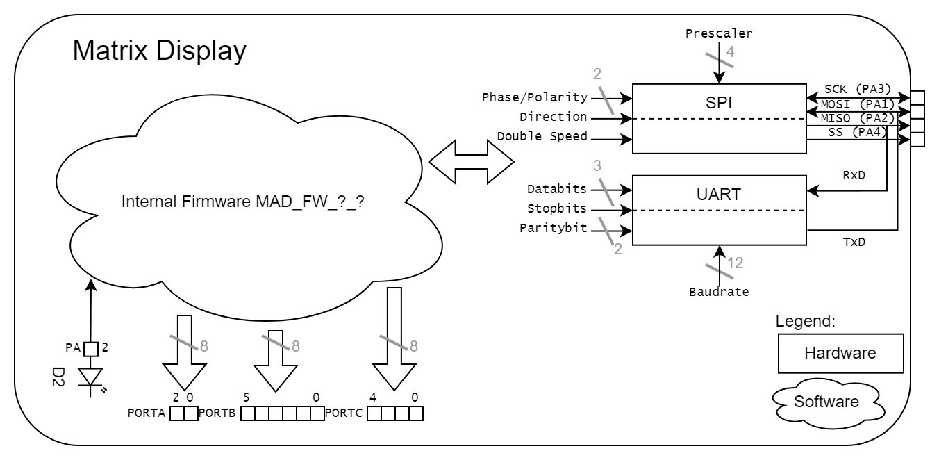
To send characters to the display over UART connect an USB/UART converter to the PC and make a bridge beween GND and SS (CS) before powering up the display. Start a terminal software on the computer (e.g. Teraterm) and setup the following settings:
| Name | Value |
|---|---|
| PORT | COM? |
| BAUD | 9600 |
| DATABITS | 8 |
| PARITY | NONE |
| STOPBITS | 1 |
| FLOWCTRL | NONE |
#      +---------------------+                                +---------------------+
#      |    MAD - Display    |                                |                     |
#    +-+-+                 +-+-+                              | +-----------------+ |
#    | 1 | VCC         VCC | 1 +-------+    +----------+      | | TeraTerm        | |
#    | 2 | UPDI       UPDI | 2 |       |    |   U  +---+---+  | | ~~~~~~~~        | |
#    | 3 | SI           SO | 3 +-----+ |    |   S  |  USB  |--+ | ~~~~~           | |
#    | 4 | SCK         SCK | 4 |     | |    |   B  +---+---+  | | ~~~~~~~~~~~~    | |
#    | 5 | SS (CS)      SS | 5 +--+  | |    |   /      |      | |                 | |
# +--+ 6 | GND         GND | 6 +--+  | |    |   U      |      | +-----------------+ |
# |  +-+-+                 +-+-+     | |  +-+-+ A      |      |                     |
# |    +---------------------+       | +--+VCC| R      |      | Computer            |
# |                                  +----+TxD| T      |      |                     |
# |                                       |RxD| +------+      +---------------------+
# +---------------------------------------+GND| |5V/3V3|
#                                         +-+-+ +------+
# +----+-----+The firmware itself contains some demos how to use the display over spi. The demo software itself is written for an ATmega16A. To test the display a connection to the spi pins between the display and the ATmega16Ais necessary.
# ~------------+
# ~          +-+-+
# ~          |VCC+------+
# ~          +-+-+       \        +---------------------+
# ~            |          \       |     MAD - Display   |
# ~  A       +-+-+         \    +-+-+                 +-+-+
# ~  T   [7] | P +- SCK -+  +---+ 1 | VCC         VCC | 1 |
# ~  M       | O |        \     | 2 | UPDI       UPDI | 2 |
# ~  E       | R +- MOSI --\----+ 3 | SI           SO | 3 |
# ~  G       | T +-- SS -+  +---+ 4 | SCK         SCK | 4 |
# ~  A       | B |       +------+ 5 | SS (CS)      SS | 5 |
# ~          |   |           +--+ 6 | GND         GND | 6 |
# ~  1       |   |          /   +-+-+                 +-+-+
# ~  6   [0] |   |         /      |                     |
# ~  A       +-+-+        /       +---------------------+
# ~            |         /
# ~          +-+-+      /
# ~          |GND+-----+
# ~          +-+-+
# ~~~~~~~~~~~~~~ To control the display through SPI the bus of the master needs the following setup:
| Parameter | Value | Description |
|---|---|---|
| Clock | < 1Mhz | Bus clock speed should not exceed this value |
| Direction | MSB | MSB needs to be transmitted first |
| Polarity | Rising | Polarity of clock is rising _/ |
| Phase | Rising | Data is valid when clock is rising _/ |
Detail can be found here
# SPI display transmission
# _                                                SS                                                _
#  \________________________________________________________________________________________________/
#                                                 SCK
#     __    __    __    __    __    __    __    __    __    __    __    __    __    __    __    __
# ___/1 \__/2 \__/3 \__/4 \__/5 \__/6 \__/7 \__/8 \__/9 \__/10\__/11\__/12\__/13\__/14\__/15\__/16\___
#                                                 MOSI
#    __    __    __    __    __    __    __    __    __    __    __    __    __    __    __    __
# __/C \__/T \__/R \__/L \__/B \__/Y \__/T \__/E \__/D \__/A \__/T \__/A \__/B \__/Y \__/T \__/E \____
#   \__/  \__/  \__/  \__/  \__/  \__/  \__/  \__/  \__/  \__/  \__/  \__/  \__/  \__/  \__/  \__/
# [7 : 0] [7 : 0]To enable a bit it needs to be set to on ($1=ON$). To disable a bit it is necessary to set it to off ($0=OFF$).
| Control-Byte | Data-Bit(s) | Description |
|---|---|---|
0x00 | 0xXX | No operation |
0x01 | [4:0] | ROW1 LEDs |
| ... | ... | ... |
0x07 | [4:0] | ROW7 LEDs |
0x08 | [6:0] | Show ASCII character on display |
0x10 | 0xXX | Clear buffer |
0x1F | [0] | Enable display |
0x20 | 0xXX | Copy EEPROM address (0) to display |
| ... | ... | ... |
0x2F | 0xXX | Copy EEPROM address (15) to display |
0x30 | 0xXX | Copy Display content to EEPROM address (0) |
| ... | ... | ... |
0x3F | 0xXX | Copy Display content to EEPROM address (15) |
0xF0 | 0xXX | Display refresh rate LOW byte |
0xF1 | 0xXX | Display refresh rate HIGH byte |
0xFF | 0xXX | RESET the SPI queue |
matrix.h)With the attached demo library (MAD_LIB) it is quiet easy to use the display. To setup the matrix display library some defines needs to be adjusted.
// Setup the number of displays that are cascaded
#ifndef MATRIX_DISPLAYS
    #define MATRIX_DISPLAYS 2
#endif#include "../lib/matrix/matrix.h"
int main(void)
{
matrix_init();
matrix_reset();
_delay_ms(MATRIX_RESET_RECOVERY_TIME_MS);
matrix_enable();
matrix_char(1, 'A');
_delay_ms(1000);
matrix_char(2, 'B');
matrix_frame(buffer);
// ...
}| Type | Link | Description |
|---|---|---|
| ATtiny406 | ATtiny microcontroller | |
| ATtiny1606 | ATtiny microcontroller | |
| ATmega16A | Microchip ATmega16A Datasheet | |
| TA20-11SRWA | Dot Matrix Dispaly | |
| Atmel ICE | Atmel ICE datasheet | |
| UPDI | web | UPDI-Adapter with AVR-Dude |
| Microchip Studio | web | Download page for Microchip Studio |
| KiCAD | web | KiCAD project page |
| FreeCAD | web | FreeCAD project page |
| TeraTerm | web | Terminal software for UART |
R. GAECHTER
| Qty | Value | Footprint | References |
|---|---|---|---|
| 7 | 15 | Resistor_SMD:R_1206_3216Metric | R2, R3, R4, R5, R6, R7, R8 |
| 7 | AO3416A | Package_TO_SOT_SMD:SOT-23 | Q1, Q3, Q5, Q7, Q9, Q11, Q12 |
| 7 | TestPoint_Probe | TestPoint:TestPoint_Pad_D1.0mm | TP1, TP2, TP3, TP4, TP5, TP6, TP7 |
| 5 | AO3419A | Package_TO_SOT_SMD:SOT-23 | Q2, Q4, Q6, Q8, Q10 |
| 2 | 10u | Capacitor_Tantalum_SMD:CP_EIA-6032-28_Kemet-C | C1, C2 |
| 2 | M3 | MountingHole:MountingHole_3.2mm_M3_DIN965_Pad | H1, H2 |
| 1 | 100n | Capacitor_SMD:C_1206_3216Metric | C3 |
| 1 | 10k | Resistor_SMD:R_1206_3216Metric | R10 |
| 1 | 180 | Resistor_SMD:R_1206_3216Metric | R9 |
| 1 | 330 | Resistor_SMD:R_1206_3216Metric | R1 |
| 1 | ATtiny__06-S | Package_SO:SOIC-20W_7.5x12.8mm_P1.27mm | U1 |
| 1 | BIN | Symbol:WEEE-Logo_4.2x6mm_SilkScreen | FID3 |
| 1 | BZV55B5V6 | Diode_SMD:D_MiniMELF | D3 |
| 1 | Conn_01x06_Pin | Connector_PinHeader_2.54mm:PinHeader_1x06_P2.54mm_Horizontal | J1 |
| 1 | Conn_01x06_Socket | Connector_PinSocket_2.54mm:PinSocket_1x06_P2.54mm_Horizontal | J2 |
| 1 | ESD | Symbol:ESD-Logo_6.6x6mm_SilkScreen | FID1 |
| 1 | Fuse | Fuse:Fuse_1206_3216Metric | F1 |
| 1 | Jumper_2_Open | Connector_PinHeader_2.54mm:PinHeader_1x02_P2.54mm_Horizontal | JP1 |
| 1 | LED | LED_SMD:LED_1206_3216Metric | D2 |
| 1 | OH | Symbol:OSHW-Logo_5.7x6mm_SilkScreen | FID2 |
| 1 | QR | Images:QR_0x007e | FID4 |
| 1 | SW_Push | Button_Switch_SMD:SW_SPST_PTS645 | SW1 |
| 1 | TA20-11SRWA | Display_Matrix:LED_TA20-11SRWA | D1 |
| 1 | n.B. | Capacitor_SMD:C_1206_3216Metric | C5 |
It measures 36 × 47 mm and has 2 copper layers, 1.6 mm thick.
48 parts, built around the AO3416A, BZV55B5V6 and TA20-11SRWA. The full list of its parts is on this page, with links to each part's symbol and footprint where PCBKit's library has them.
From the 0x007E/mad repository on GitHub, at the commit this page was made from: the board is pcb/MAD.kicad_pcb and its schematic pcb/MAD.kicad_sch. PCBKit opens the board in the browser, with nothing to install.
Its repository states no licence, so its author keeps all rights: ask 0x007E before reusing the design.


