

2 layers76.2 × 50.8 mm

 0x007E/gca
Gamecard Adapter
Gca is an open-source printed circuit board by 0x007E, from the 0x007E/gca repository on GitHub. It is a 2-layer board of 28.4 × 17 mm with 18 parts on 10 nets, routed with 31 tracks and 27 vias.
It is built around the AT24CM02-SSHM-T. Its parts include 6 resistors, 2 capacitors, 1 IC, 1 connector and 1 switch.


GCA - Game Card AdapterThe GCA is a board with a AT24CM0X EEPROM or any other compatible EEPROM. The board itself can be driven with a voltage from 3V3-5V and is used chainload games onto the GamePad over the integrated bootloader (currently under development).
| Experience | Level |
|---|---|
| Soldering | |
| Mechanical |
| Type | File | Description |
|---|---|---|
| Schematic | pdf / cadlab | Schematic files |
| Board | pdf / cadlab | Board file |
| Drill | Drill file | |
| BoM | xlsx / html | Bill of Material as Excel/interactive HTML |
| PCB | zip / tar | KiCAD/Gerber/BoM/Drill files |
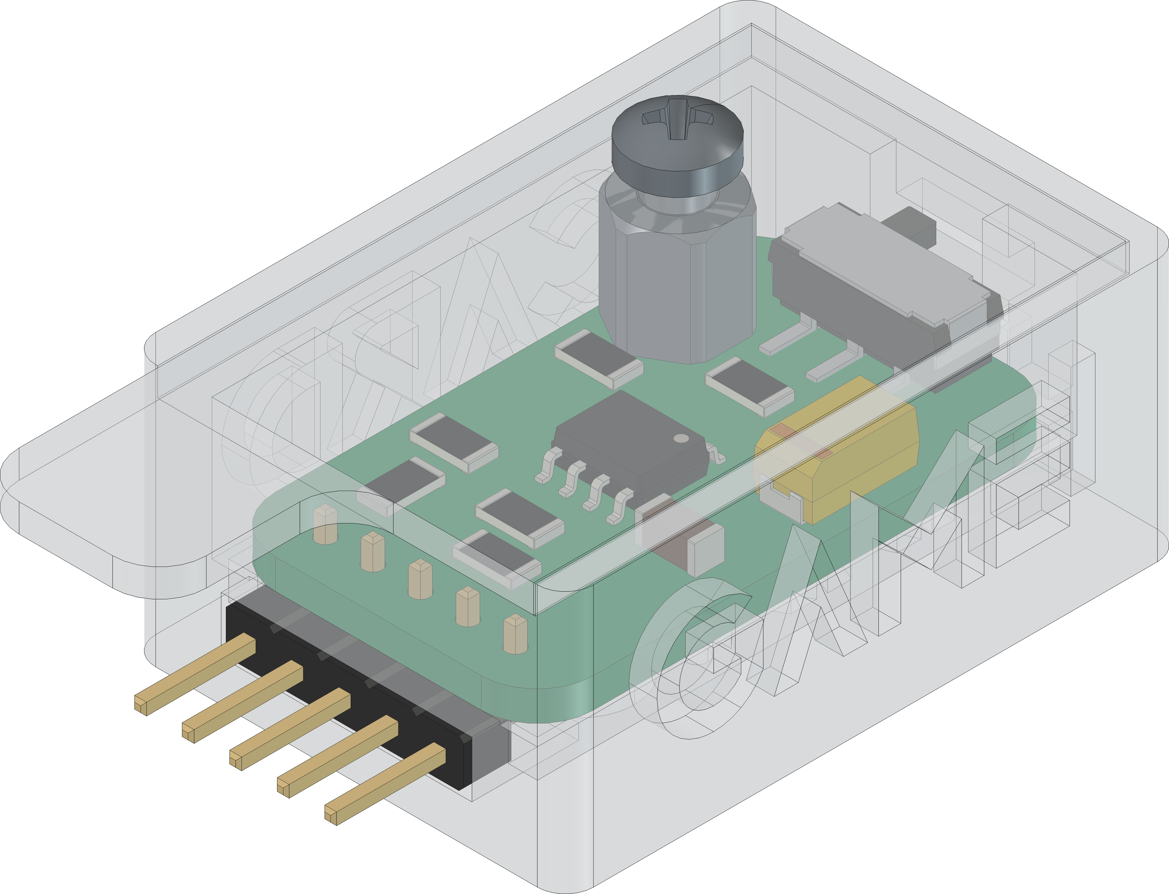
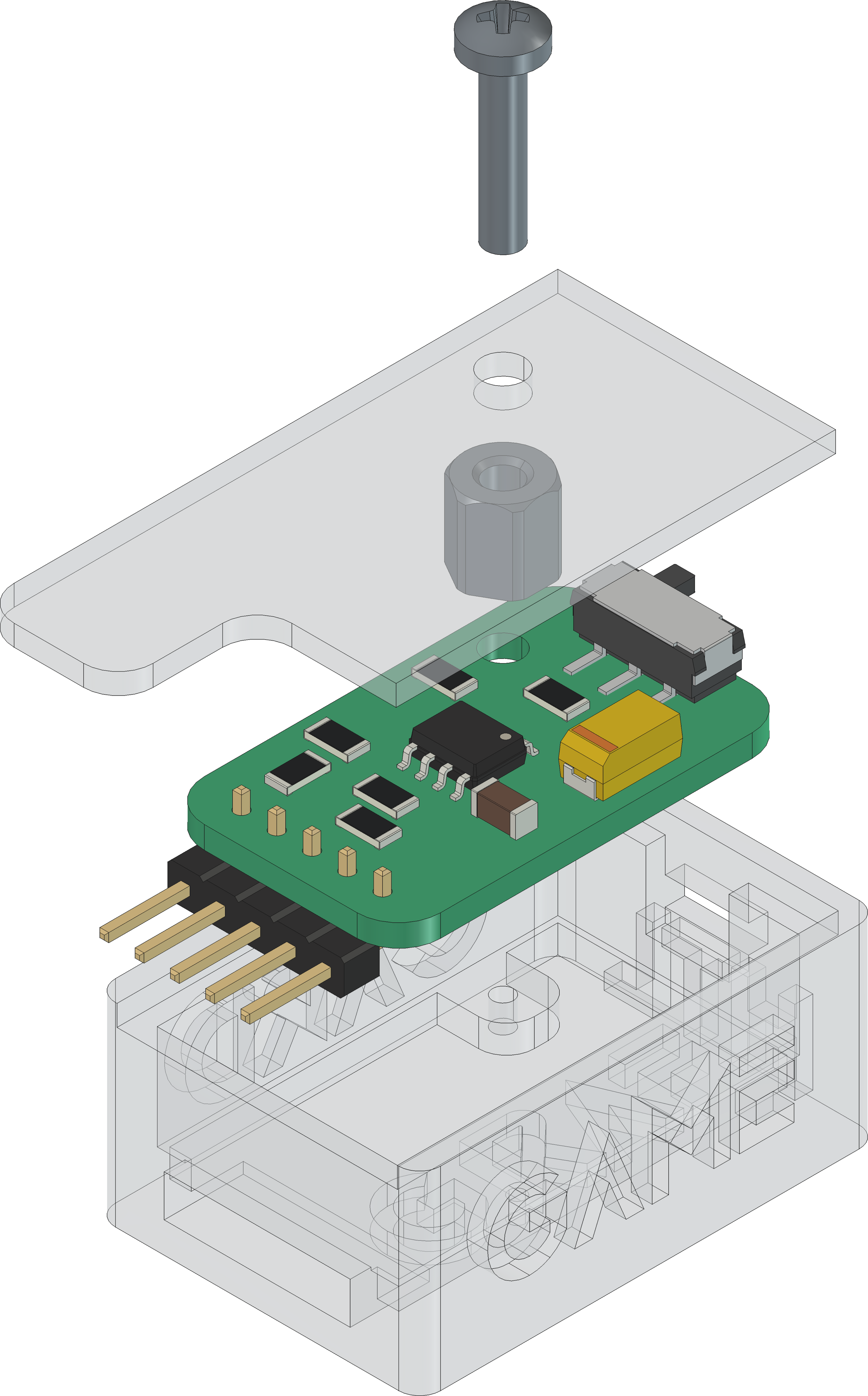
| Mechanical | zip / tar | FreeCAD/Housing and PCB (STEP/STL) files |
The pcb is created with KiCAD, the housing with FreeCAD. All files are built with github actions so that they are ready for a production environment.
The circuit board is populated on both sides (Top, Bottom). The best way for soldering the SMD components is within a vapor phase soldering system and for the THT components with a standard soldering system.


The housing has a tolerance of 0.2mm on each side of the case. So the pcb should fit perfectly in the housing. The tolerance can be modified with FreeCAD in the Parameter Spreadsheet.
| Type | Link | Description |
|---|---|---|
| AT24CM02 | 2-MBit serial EEPROM dataseheet | |
| AT24CM01 | 1-MBit serial EEPROM datasheet |
| Qty | Value | Footprint | References |
|---|---|---|---|
| 3 | 10k | Resistor_SMD:R_1206_3216Metric | R1, R2, R3 |
| 2 | 3k3 | Resistor_SMD:R_1206_3216Metric | R4, R5 |
| 2 | SolderJumper_2_Open | Jumper:SolderJumper-2_P1.3mm_Open_RoundedPad1.0x1.5mm | JP1, JP2 |
| 1 | 0 | Resistor_SMD:R_1206_3216Metric | R6 |
| 1 | 100n | Capacitor_SMD:C_1206_3216Metric | C2 |
| 1 | 10u | Capacitor_Tantalum_SMD:CP_EIA-6032-28_Kemet-C | C1 |
| 1 | AT24CM02-SSHM | Package_SO:SOIC-8_3.9x4.9mm_P1.27mm | U1 |
| 1 | BIN | Symbol:WEEE-Logo_4.2x6mm_SilkScreen | FID3 |
| 1 | Conn_01x05_Pin | Connector_PinHeader_2.54mm:PinHeader_1x05_P2.54mm_Horizontal | J2 |
| 1 | ESD | Symbol:ESD-Logo_6.6x6mm_SilkScreen | FID1 |
| 1 | MountingHole_Pad | MountingHole:MountingHole_2.7mm_M2.5_DIN965_Pad | H1 |
| 1 | OH | Symbol:OSHW-Logo_5.7x6mm_SilkScreen | FID2 |
| 1 | QR | Images:QR_0x007e_very_small | FID4 |
| 1 | SW_SPDT | Button_Switch_SMD:SW_SPDT_CK_JS102011SAQN | SW2 |
It measures 28.4 × 17 mm and has 2 copper layers, 1.6 mm thick.
18 parts, built around the AT24CM02-SSHM-T. The full list of its parts is on this page, with links to each part's symbol and footprint where PCBKit's library has them.
From the 0x007E/gca repository on GitHub, at the commit this page was made from: the board is pcb/GCA.kicad_pcb and its schematic pcb/GCA.kicad_sch. PCBKit opens the board in the browser, with nothing to install.
Its repository states no licence, so its author keeps all rights: ask 0x007E before reusing the design.


VoronDesign/Voron-Hardware
Cool Hardware designed by the Voron Design group


hackclub/OnBoard
💡 Join 1,000 teenagers and make your first PCB with a $100 grant!

VoronDesign/Voron-Tap
Tap is a nozzle-based z-probe for the V2 and Trident printer designs. The entire toolhead moves to trigger an optical switch. Tap offers many advantages: