

2 layers25.4 × 25.4 mm

 0x007E/rcc
RGB Color Cube
Rcc is an open-source printed circuit board by 0x007E, from the 0x007E/rcc repository on GitHub. It is a 2-layer board of 25.4 × 25.4 mm with 15 parts on 12 nets, routed with 40 tracks and 28 vias.
It is built around the ATTINY402-SSN and BH-67D-5. Its parts include 3 capacitors, 3 resistors, 2 diodes, 1 IC and 1 switch. It belongs with the lEDs and displays boards and the AVR (ATmega, ATtiny) boards of this library.


RCC - RGB Color Cube
The RCC project is based on a pcb with an ATtiny402 and two RGB LEDs that are controlled via SPI-bus. The cube itself is controlled over a single push-button that enables/disables the cube and can be used to setup the color and intensity of the rgb leds.
| Experience | Level |
|---|---|
| Soldering | |
| Mechanical | |
| Software |
| Language | File | Description |
|---|---|---|
| English | Assembly of PCB/housing and programming of the RCC | |
| German | Assembly of PCB/housing and programming of the RCC |
With the RCC-Simulator different functions (e.g. power-on/-off, ...) can be simulated within a webpage.
| Type | File | Description |
|---|---|---|
| Schematic | pdf / cadlab | Schematic files |
| Board | pdf / cadlab | Board file |
| Drill | Drill file | |
| PCB | zip / tar | KiCAD/Gerber/BoM/Drill files |
| Mechanical | zip / tar | FreeCAD/Housing and PCB (STEP) files |
| Firmware | zip / tar | Firmware for ATtiny402 |
There are two parts of the hardware. The pcb and the housing of the RCC. The pcb is created with KiCAD and the housing with FreeCAD. The software is programmed with Microchip (Atmel) Studio. All files are built with github actions so that they are ready for a production environment. The housing is printed with a 3D-printer (Dremel 3D40).
The circuit board is populated on both sides (Top, Bottom). The best way for soldering the SMD components is within a vapor phase soldering system and for the THT components with a standard soldering system.


The housing has a tolerance of 0.2mm on each side of the case. So the pcb should fit perfectly in the housing. The tolerance can be modified with FreeCAD in the Parameter Spreadsheet.
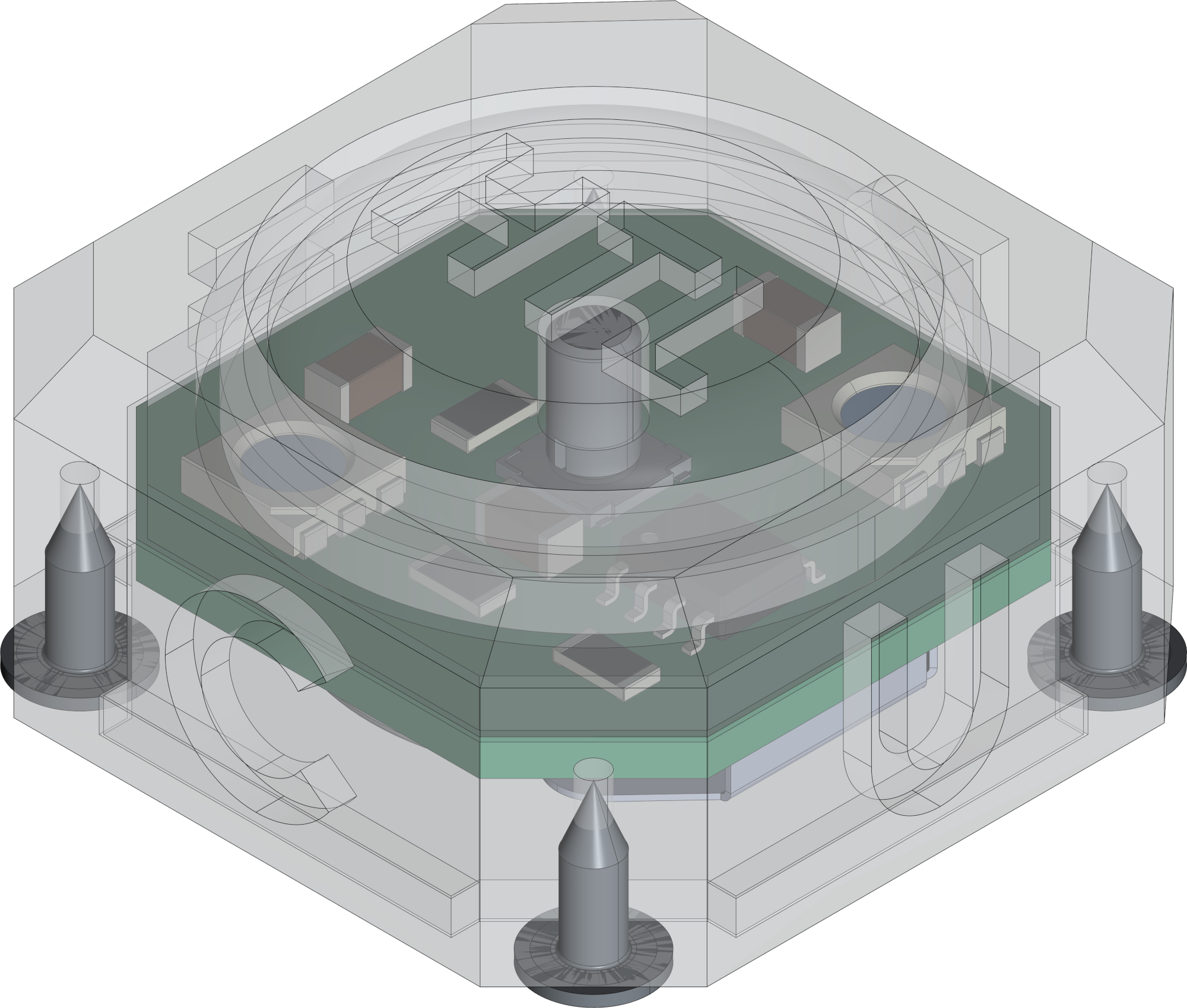
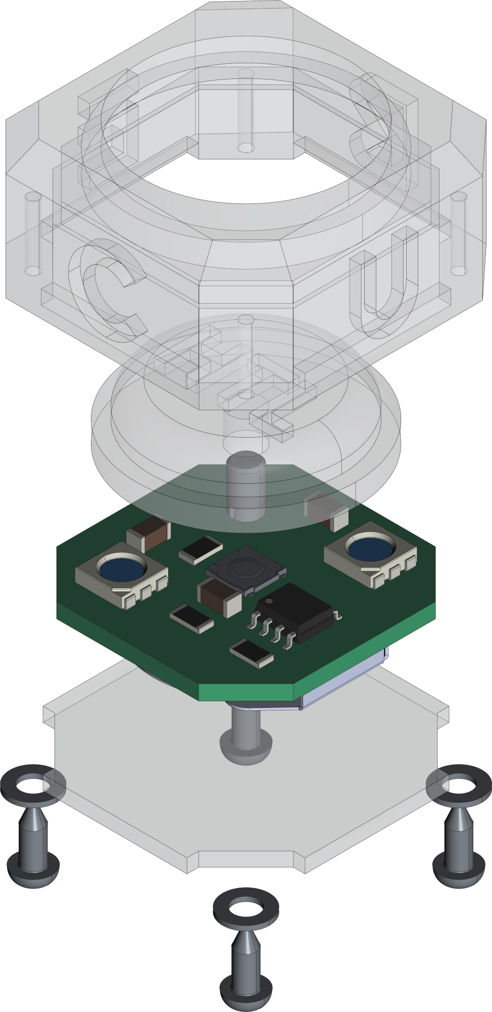
The RCC is powerd with a 3V battery (CR2032). It can be programmed over UPDI on TP1. The firmware for the cube can be downloaded in the download section.
#                                                          +-----------+      +---------------------+
#                                                          |    U  +---+---+  |                     |
#     +---------------------+                              |    S  |  USB  |--+ +-----------------+ |
#     |                     |                              |    B  +---+---+  | | AVR-Dude        | |
#     |    RCC - Color Cube |         +----------+         |    /      |      | | ~~~~~~~~        | |
#     |                  +--+--+   +--+--+  U    |         |    U      |      | | ~~~~~           | |
#     |              VCC | TP3 +---+ VCC |  P  +--+--+  +--+--+ A      |      | | ~~~~~~~~~~~~    | |
#     |              GND | TP2 +---+ GND |  D  | GND +--+ GND | R      |      | |                 | |
#     |                  +--+--+   +--+--+  I  | VCC +--+ VCC | T      |      | +-----------------+ |
#     |                     |         |        +-----+  +-----+ A      |      |                     |
#     |                  +--+--+   +--+--+     | RxD +--+ RxD | +------+      | Computer            |
#     |             UPDI | TP1 +---+ PDI |     | TxD +--+ TxD | |5V/3V3|      |                     |
#     |                  +--+--+   +--+--+     +--+--+  +--+--+ +------+      +---------------------+
#     +---------------------+         | ADAPTER   |        +----+------+
# +-----------+| Register | Value |
|---|---|
WDTCFG | 0x00 |
BODCFG | 0x00 |
OSCCFG | 0x03 |
TCD0CFG | 0x00 |
SYSCFG0 | 0xF5 |
SYSCFG1 | 0x00 |
APPEND | 0x00 |
BOOTEND | 0x00 |
The leds are controlled by SPI. The interface is displayed in the dataflow diagram. There is a pre-configured firmware to use the cube or a library to implement own solutions.
A documentation of the code can be found here https://0x007e.github.io/rcc.
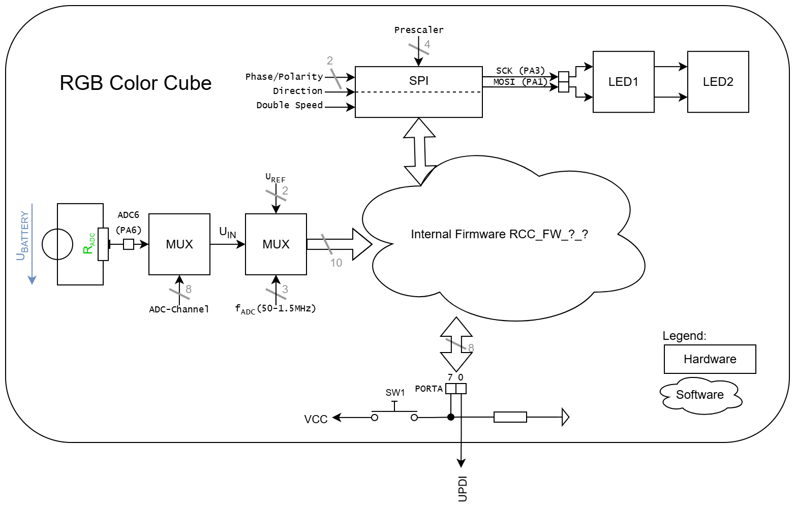
led.h)With the attached led library it is quiet easy to use the cube for own implementations. To setup the led library for the cube implement the header file.
#define F_CPU 20000000UL

#include <avr/io.h>
#include <util/delay.h>

#include "./hal/avr0/system/system.h"
#include "./led/led.h"

LED_Data led1  = {
	0x01,
	0x0F,
	0x00,
	0x0A
};

LED_Data led2  = {
	0x01,
	0x00,
	0x0F,
	0x0A
};

int main(void)
{| Type | Link | Description |
|---|---|---|
| ATtiny402 | ATtiny microcontroller | |
| T3A33BRG | RGB Color LED | |
| Atmel ICE | Atmel ICE datasheet | |
| UPDI | web | UPDI-Adapter with AVR-Dude |
| Microchip Studio | web | Download page for Microchip Studio |
| KiCAD | web | KiCAD project page |
| FreeCAD | web | FreeCAD project page |
R. GAECHTER
| Qty | Value | Footprint | References |
|---|---|---|---|
| 3 | 100n | Capacitor_SMD:C_1206_3216Metric | C1, C2, C3 |
| 3 | TestPoint | TestPoint:TestPoint_Pad_D1.5mm | TP1, TP2, TP3 |
| 2 | 1Meg | Resistor_SMD:R_1206_3216Metric | R1, R2 |
| 2 | APA102 | LED_SMD:LED_RGB_5050-6 | D1, D2 |
| 1 | 10k | Resistor_SMD:R_1206_3216Metric | R3 |
| 1 | ATtiny402-SS | Package_SO:SOIC-8_3.9x4.9mm_P1.27mm | U1 |
| 1 | BH-67D-5 | Battery_BH:BAT_BH-67D-5 | BT1 |
| 1 | QR | Images:QR_0x007e_small | FID4 |
| 1 | SW_MEC_5E | PTS530:SW_PTS530_GK055_SMTR_LFS | SW1 |
It measures 25.4 × 25.4 mm and has 2 copper layers, 1.6 mm thick.
15 parts, built around the ATTINY402-SSN and BH-67D-5. The full list of its parts is on this page, with links to each part's symbol and footprint where PCBKit's library has them.
From the 0x007E/rcc repository on GitHub, at the commit this page was made from: the board is pcb/RCC.kicad_pcb and its schematic pcb/RCC.kicad_sch. PCBKit opens the board in the browser, with nothing to install.
Its repository states no licence, so its author keeps all rights: ask 0x007E before reusing the design.


PocketConcepts/Pocket_PSU
A variable current & voltage PSU with 3S lipo charging, balancing, and protection circuit using PPS.

k-takata/PCB_avr_dx_unbricker
UPDI High Voltage programmer for AVR Dx/Ex series

HazeCore/Nametag_Hardware
This is the hardware for out Nametag Badge for Chaos Communication Camp 2023. You can find more information about the Project at https://hazeco.re/cccamp-nametag/.
markusgruen/DccFunctionDecoder
Open source, Arduino-based DCC function decoder
