
2 layers130 × 95 mm

Fanmade of E.LB.E.R.R. robot by LightsAreOff
Esp is an open-source printed circuit board by 0Zane, from the 0Zane/E.L.B.E.R.R repository on GitHub, published under the MIT licence. It is a 2-layer board of 100 × 80 mm with 94 parts on 90 nets, routed with 467 tracks and 178 vias.
It is built around the ESP32-S3-WROOM-1-N8, NRF24L01 and BME280, with the AMS1117-3.3 and VL53L0X among its other parts. Its parts include 25 capacitors, 24 resistors, 12 diodes, 9 connectors and 6 ICs. It belongs with the robots and motor control boards and the ESP32 boards of this library.



A fanmade animatronic robot powered by local AI, embedded control systems, and custom hardware.






E.L.B.E.R.R. is a fanmade animatronic project inspired by the robot featured in the animations from LIGHTS ARE OFF.
The goal of this project is to recreate the character as a physical animatronic robot using a custom local AI system, embedded motor control, sensors, and purpose-built hardware. E.L.B.E.R.R. is designed as a self-contained robot that can process information locally, control its own actuators, and respond through real-time embedded systems.
This is an unofficial fan project. It is not affiliated with, endorsed by, or produced by LIGHTS ARE OFF.
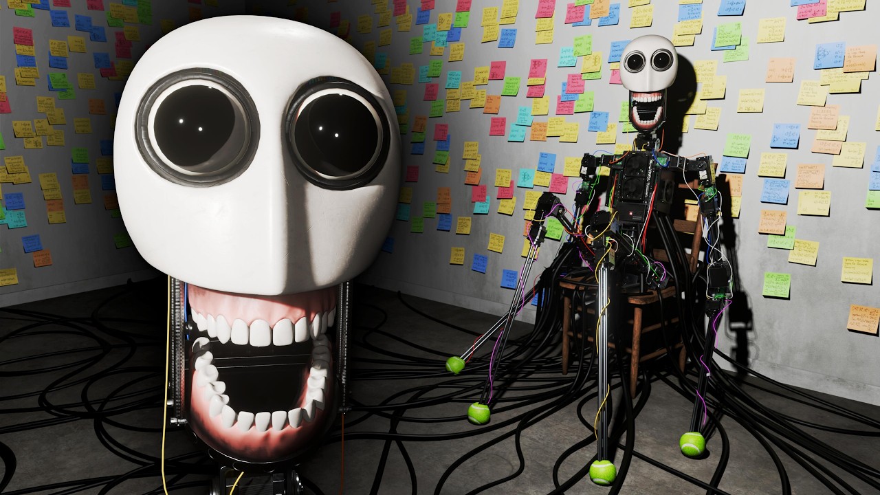
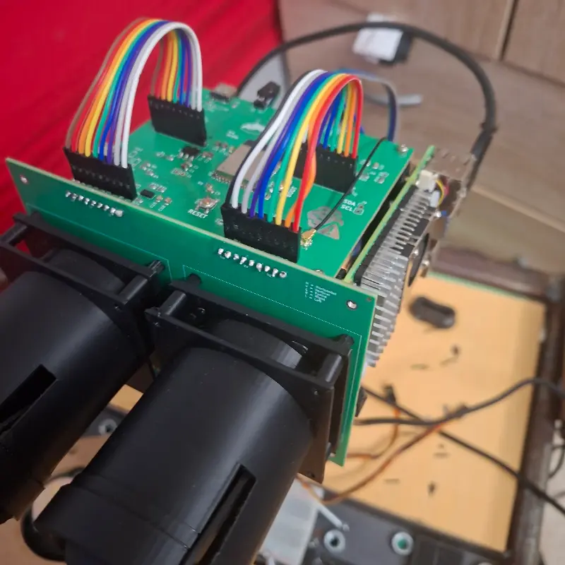
A few photos from the assembled robot, scaled for cleaner viewing in the repository.
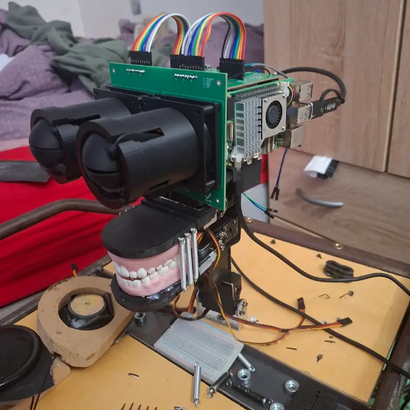 | 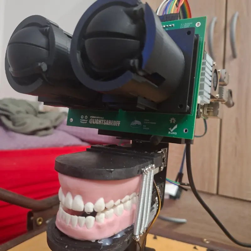 |
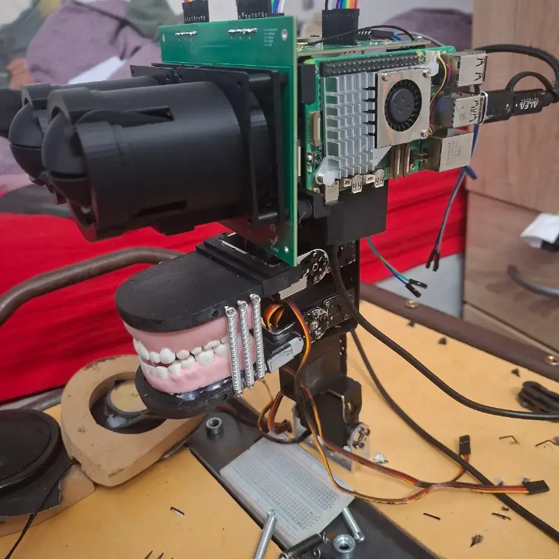 |  |
E.L.B.E.R.R. is built around a three-processor architecture:
This separation allows each processor to focus on a specific task while keeping motion control isolated from higher-level software.
The Raspberry Pi 5, ESP32-S3, and STM32 communicate with one another over UART.
flowchart LR
  Camera[Camera] --> Pi[Raspberry Pi 5]
  Mic[Microphone] --> Pi
  Other[Embedded Sensors] --> ESP

  Pi <-->|UART| ESP[ESP32-S3]

  Pi --> AI[Local AI System]
  AI --> Behavior[Behavior Engine]

  Pi <-->|UART| STM[STM32]
  STM --> Servos[Servos]
STM --> Actuators[Animatronic Actuators]| Subsystem | Component | Purpose |
|---|---|---|
| Main computer | Raspberry Pi 5 | Local AI, behavior logic, planning, vision processing, networking, and system orchestration |
| Sensor & RF controller | ESP32-S3 | Environmental sensors, wireless communication, RF capabilities, and data collection |
| Motion controller | STM32 | Real-time servo control, actuator control, deterministic timing, and motion safety |
| Mechanical system | Animatronic frame | Physical movement, expression, and character presence |
| Sensors | Cameras, microphones, IMUs, and embedded sensors | Environmental input and interaction data |
| PCB design | KiCad | Custom circuit design, wiring organization, and hardware integration |
| Firmware | C++ | Embedded software for STM32 and ESP32-S3 |
The Raspberry Pi 5 is the central computer of E.L.B.E.R.R.
Its responsibilities include:
The Pi is responsible for what the robot thinks.
The ESP32-S3 is dedicated to sensing and wireless communication.
Its responsibilities include:
The ESP32-S3 is responsible for what the robot perceives and how it communicates with external devices.
The STM32 is dedicated to real-time motion control.
Its responsibilities include:
The STM32 is responsible for how the robot moves.
The design files in the repository include the core hardware schematics and module layouts for the robot control system.
ESP modules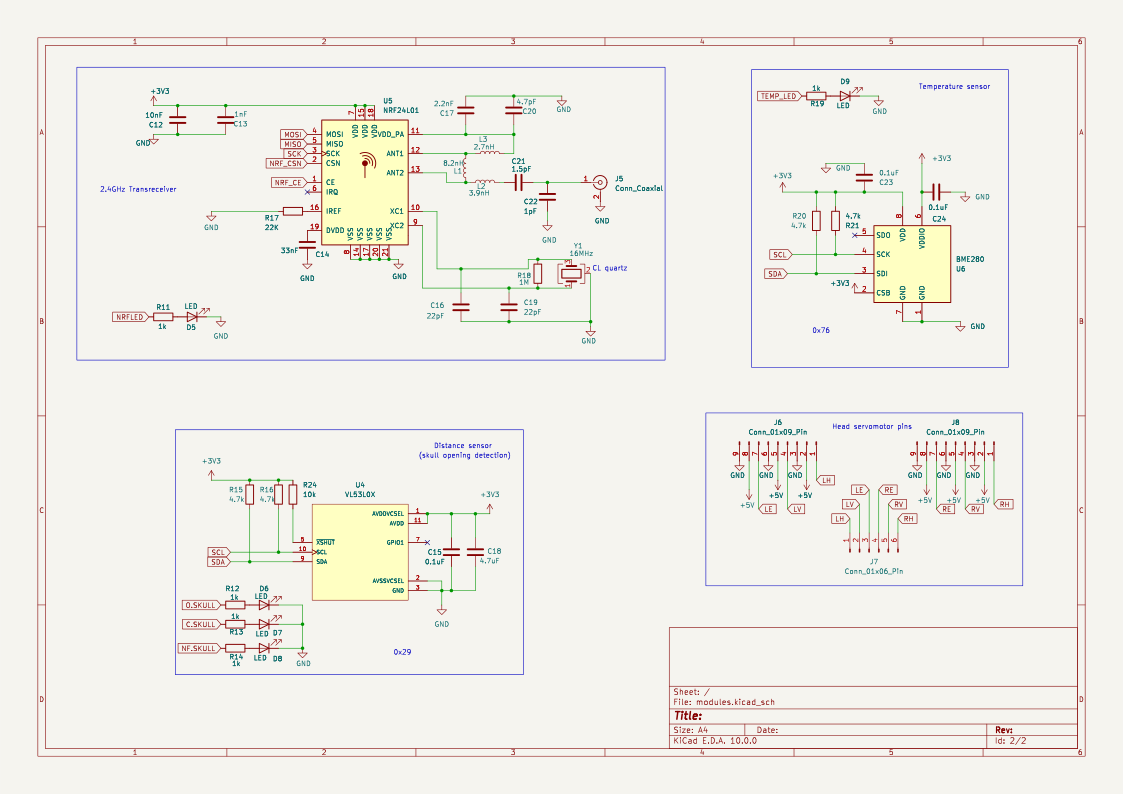 | ESP32-S3 board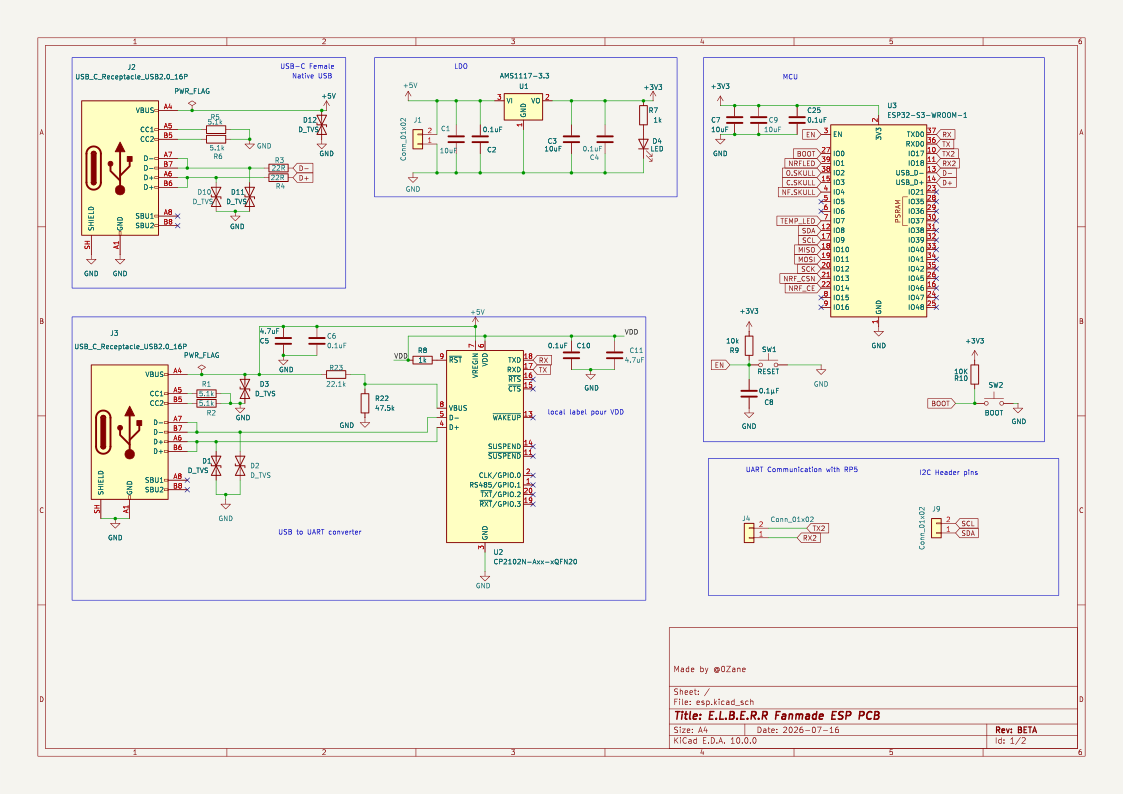 | Eye module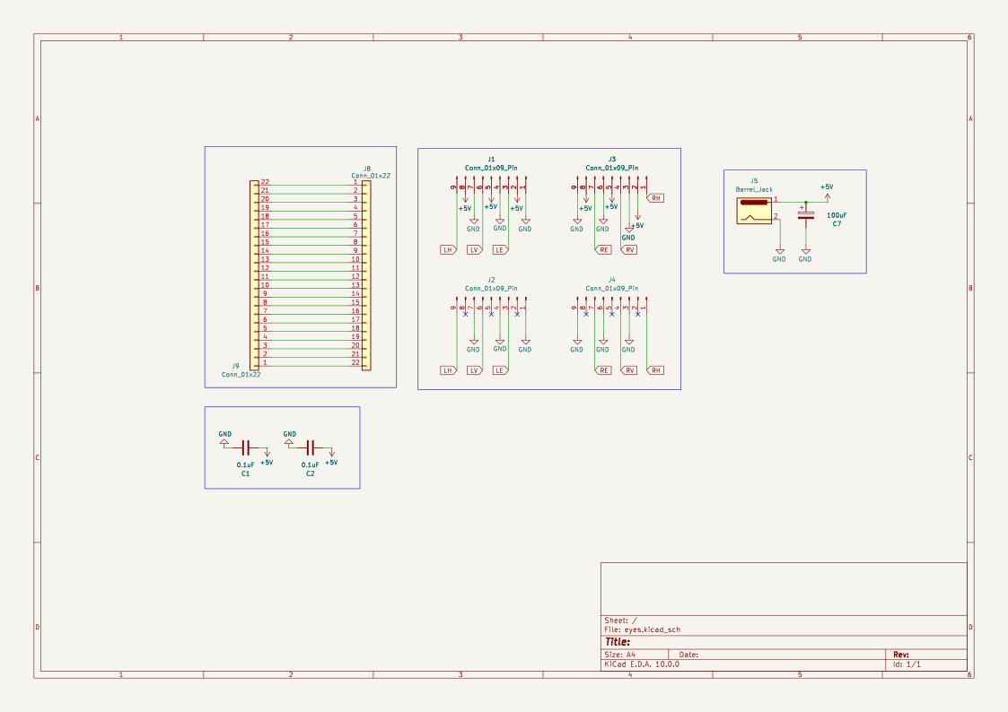 |
E.L.B.E.R.R/
|-- 3dmodels/
|-- esp32-firmware/
|   |-- include/
|   |-- lib/
|   |-- src/
|   |-- test/
|   `-- platformio.ini
|-- hardware/
|   |-- README.md
|   |-- esp/
|   |   |-- esp.kicad_pro
|   |   |-- esp.kicad_sch
|   |   |-- esp.kicad_pcb
|   |   |-- bom.csv
|   |   |-- production/
|   |   `-- esp-backups/
|   |-- eyes/
|   |   |-- eyes.kicad_pro
|   |   |-- eyes.kicad_sch
|   |   |-- eyes.kicad_pcb
|   |   |-- bom.csv
|   |   |-- production/
| | `-- eyes-backups/| Area | Technology |
|---|---|
| Main compute | Raspberry Pi 5 |
| Sensor processor | ESP32-S3 |
| Motion controller | STM32 |
| Firmware | C++ |
| PCB design | KiCad |
| 3D modeling | Fusion 360 |
| AI | Local custom AI system |
| Architecture | Distributed embedded system |
This project is inspired by the robot created in the animations from LIGHTS ARE OFF.
E.L.B.E.R.R. is a fanmade physical interpretation of that concept, built as a personal robotics, AI, and embedded systems project.
Special thanks to the people who helped along the way:
This project is licensed under the MIT License.
See the LICENSE file for details.
| Qty | Value | Footprint | References |
|---|---|---|---|
| 8 | 0.1uF | Capacitor_SMD:C_0805_2012Metric | C2, C4, C6, C10, C15, C23, C24, C25 |
| 7 | 1k | Resistor_SMD:R_0805_2012Metric | R7, R8, R11, R12, R13, R14, R19 |
| 6 | D_TVS | Diode_SMD:D_SOD-123 | D1, D2, D3, D10, D11, D12 |
| 6 | LED | LED_SMD:LED_0603_1608Metric | D4, D5, D6, D7, D8, D9 |
| 4 | , , , | ||
| 4 | 10uF | Capacitor_SMD:C_0805_2012Metric | C1, C3, C7, C9 |
| 4 | 4.7k | Resistor_SMD:R_0805_2012Metric | R15, R16, R20, R21 |
| 4 | 5.1k | Resistor_SMD:R_0805_2012Metric | R1, R2, R5, R6 |
| 4 | LOGO | LOGO | G***, G***, G***, G*** |
| 3 | 4.7uF | Capacitor_SMD:C_0805_2012Metric | C5, C11, C18 |
| 3 | Conn_01x02 | Connector_PinHeader_2.54mm:PinHeader_1x02_P2.54mm_Vertical | J1, J4, J9 |
| 2 | 10k | Resistor_SMD:R_0805_2012Metric | R9, R24 |
| 2 | 22R | Resistor_SMD:R_0805_2012Metric | R3, R4 |
| 2 | 22pF | Capacitor_SMD:C_0603_1608Metric | C16, C19 |
| 2 | Conn_01x09_Pin | Connector_PinHeader_2.54mm:PinHeader_1x09_P2.54mm_Vertical | J6, J8 |
| 2 | USB_C_Receptacle_USB2.0_16P | Connector_USB:USB_C_Receptacle_HCTL_HC-TYPE-C-16P-01A | J2, J3 |
| 1 | 0.1µF | Capacitor_SMD:C_0805_2012Metric | C8 |
| 1 | 1.5pF | Capacitor_SMD:C_0603_1608Metric | C21 |
| 1 | 10K | Resistor_SMD:R_0805_2012Metric | R10 |
| 1 | 10nF | Capacitor_SMD:C_0603_1608Metric | C12 |
| 1 | 16MHz | Crystal:Crystal_SMD_3225-4Pin_3.2x2.5mm | Y1 |
| 1 | 1M | Resistor_SMD:R_0805_2012Metric | R18 |
| 1 | 1nF | Capacitor_SMD:C_0603_1608Metric | C13 |
| 1 | 1pF | Capacitor_SMD:C_0603_1608Metric | C22 |
| 1 | 2.2nF | Capacitor_SMD:C_0805_2012Metric | C17 |
| 1 | 2.7nH | Inductor_SMD:L_0603_1608Metric | L3 |
| 1 | 22.1k | Resistor_SMD:R_0805_2012Metric | R23 |
| 1 | 22K | Resistor_SMD:R_0603_1608Metric | R17 |
| 1 | 3.9nH | Inductor_SMD:L_0603_1608Metric | L2 |
| 1 | 33nF | Capacitor_SMD:C_0603_1608Metric | C14 |
| 1 | 4.7pF | Capacitor_SMD:C_0805_2012Metric | C20 |
| 1 | 47.5k | Resistor_SMD:R_0805_2012Metric | R22 |
| 1 | 8.2nH | Inductor_SMD:L_0603_1608Metric | L1 |
| 1 | AMS1117-3.3 | Package_TO_SOT_SMD:SOT-223-3_TabPin2 | U1 |
| 1 | BME280 | Package_LGA:Bosch_LGA-8_2.5x2.5mm_P0.65mm_ClockwisePinNumbering | U6 |
| 1 | BOOT | Button_Switch_SMD:SW_SPST_SKQG_WithStem | SW2 |
| 1 | CP2102N-Axx-xQFN20 | Package_DFN_QFN:SiliconLabs_QFN-20-1EP_3x3mm_P0.5mm_EP1.8x1.8mm | U2 |
| 1 | Conn_01x06_Pin | Connector_PinHeader_2.54mm:PinHeader_1x06_P2.54mm_Vertical | J7 |
| 1 | Conn_Coaxial | Connector_Coaxial:U.FL_Molex_MCRF_73412-0110_Vertical | J5 |
| 1 | ESP32-S3-WROOM-1 | RF_Module:ESP32-S3-WROOM-1 | U3 |
| 1 | NRF24L01 | Package_DFN_QFN:QFN-20-1EP_4x4mm_P0.5mm_EP2.5x2.5mm | U5 |
| 1 | RESET | Button_Switch_SMD:SW_SPST_SKQG_WithStem | SW1 |
| 1 | VL53L0X | VL53L0X:SENSOR_VL53L0X | U4 |
The 90 most common of 94 parts.


ODARI-CHARLES1/iot_device_pcb
Hardware design for a air conditioner pcb design using Kicad software. This is for learning purpose only not manufacturable.

JimiR0/TVT23SPL_R8_Weather_station
The electronics application project is part of the second-year studies in the Bachelor’s Degree in Information and Communication Technology.


AlexOpanasevych/beetroot_embedded_course
Module tasks for Beetroot Embedded course

AlisonTristao/KynoWave
Dispositivo IoT para monitoramento do nivel de ruído em ambientes (2º lugar na maratona de inovação 2026/1 - Arena Ação Junior)

ficosta/Guardian-Sense
Guardian-Sense is a versatile hardware project based on the ESP32-S3, designed to monitor environmental conditions and provide real-time data to Zabbix.
It measures 100 × 80 mm and has 2 copper layers, 1.6 mm thick.
94 parts, built around the ESP32-S3-WROOM-1-N8, NRF24L01, BME280 and AMS1117-3.3. The full list of its parts is on this page, with links to each part's symbol and footprint where PCBKit's library has them.
From the 0Zane/E.L.B.E.R.R repository on GitHub, at the commit this page was made from: the board is hardware/esp/esp.kicad_pcb and its schematic hardware/esp/esp.kicad_sch. PCBKit opens the board in the browser, with nothing to install.
Its repository publishes it under the MIT licence: you may reuse it on that licence's terms (keep the author's notice, and for a copyleft licence share your changes alike).