2 layers123 × 87.5 mm
FastLOGIC
Neumi/fastLOGIC
An affordable Arduino-based board designed for straightforward (industrial) logic control, ideal for building small-scale automation and control solutions.
180 parts23MIT

 AlisonTristao/KynoWave
Dispositivo IoT para monitoramento do nivel de ruído em ambientes (2º lugar na maratona de inovação 2026/1 - Arena Ação Junior)
KynoWave is an open-source printed circuit board by AlisonTristao, from the AlisonTristao/KynoWave repository on GitHub. It is a 2-layer board of 100 × 55 mm with 85 parts on 79 nets, routed with 640 tracks and 109 vias.
It is built around the ESP32-S3-WROOM-1-N8, BME280 and MAX4466EXK+T, with the MEM2075-00-140-01-A, R1M and AMS1117-3.3 among its other parts. Its parts include 37 resistors, 15 capacitors, 6 connectors, 4 diodes and 2 ICs. It belongs with the ESP32 boards of this library.


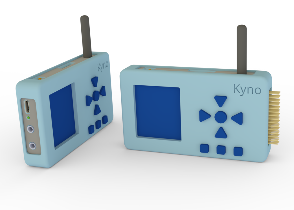
O KynoWave é um projeto de hardware focado na monitorização de ruído acústico em ambientes. Desenvolvido em torno do microcontrolador ESP32-S3.
O projeto foi desenvolvido para participar do desafio da Maratona de Inovação 2026/1, realizada no evento Arena Ação Jr.
Todo o desenvolvimento de hardware e software foi realizado em menos de um mês, dentro do prazo proposto pelo desafio, e o projeto conquistou o 2º lugar na competição.
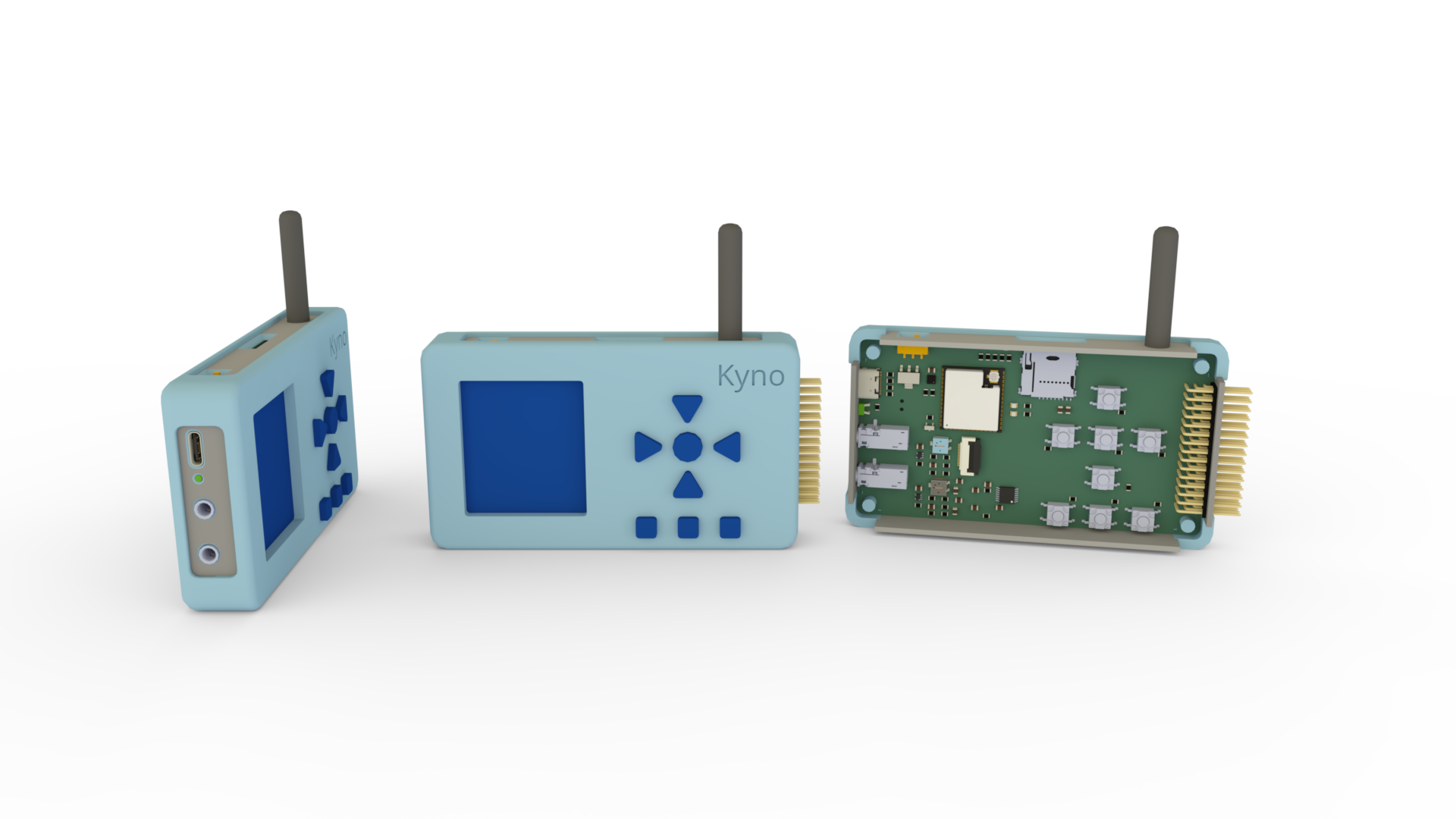
Abaixo, a fotografia detalhada da PCB:
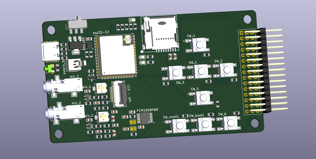
| Qty | Value | Footprint | References |
|---|---|---|---|
| 12 | pull_up | Resistor_SMD:R_0805_2012Metric | R5, R6, R26, R27, R28, R29, R36, R37, R38, R39, R40, R41 |
| 8 | SW_6mm_SMD | Library:SW_TS08-66-43-BK-160-SMT-67-TR | SW_1, SW_2, SW_3, SW_4, SW_5, SW_6, SW_boot1, SW_reset1 |
| 4 | R1M | Resistor_SMD:R_0805_2012Metric | R14, R15, R21, R22 |
| 4 | R2k | Resistor_SMD:R_0805_2012Metric | R16, R18, R19, R20 |
| 3 | C0.1uF | Capacitor_SMD:C_0805_2012Metric | C4, C5, C9 |
| 3 | C10nF | Capacitor_SMD:C_0805_2012Metric | C3, C6, C15 |
| 3 | Conn_01x15_Pin | Connector_PinHeader_2.54mm:PinHeader_1x15_P2.54mm_Vertical | J2, J3, J4 |
| 3 | LED | LED_SMD:LED_0805_2012Metric | D4, D5, D6 |
| 3 | R220 | Resistor_SMD:R_0805_2012Metric_Pad1.20x1.40mm_HandSolder | R12, R17, R24 |
| 2 | C100pF | Capacitor_SMD:C_0805_2012Metric | C1, C8 |
| 2 | C1pF | Capacitor_SMD:C_0805_2012Metric | C2, C7 |
| 2 | C1uF | Capacitor_SMD:C_0805_2012Metric | C11, C13 |
| 2 | C4.7pF | Capacitor_SMD:C_0805_2012Metric | C12, C14 |
| 2 | MAX4466EXK | Library:SOT65P210X110-5N | amplificador_mic1, amplificador_mic2 |
| 2 | R10k | Resistor_SMD:R_0805_2012Metric | R11, R25 |
| 2 | R200k | Potentiometer_SMD:Potentiometer_Bourns_3314G_Vertical | RV1, RV2 |
| 2 | R20k | Resistor_SMD:R_0805_2012Metric | R13, R31 |
| 2 | R22 | Resistor_SMD:R_0805_2012Metric | R3, R4 |
| 2 | R330 | Resistor_SMD:R_0805_2012Metric | R32, R33 |
| 2 | R4.7k | Resistor_SMD:R_0805_2012Metric | R34, R35 |
| 2 | R5.1k | Resistor_SMD:R_0805_2012Metric | R1, R2 |
| 2 | conector_p2 | Connector_Audio:Jack_3.5mm_CUI_SJ-3523-SMT_Horizontal | AudioPlug1, AudioPlug2 |
| 2 | off | Jumper:SolderJumper-2_P1.3mm_Open_TrianglePad1.0x1.5mm | JP1, JP2 |
| 1 | AMS1117-3.3 | Package_TO_SOT_SMD:SOT-223-3_TabPin2 | step_down_3.3 |
| 1 | AO3400A | Package_TO_SOT_SMD:SOT-23 | Q1 |
| 1 | BME280 | Package_LGA:Bosch_LGA-8_2.5x2.5mm_P0.65mm_ClockwisePinNumbering | U2 |
| 1 | C10uF | Capacitor_SMD:C_0805_2012Metric | C10 |
| 1 | Conn_01x02_Pin | Connector_Molex:Molex_KK-254_AE-6410-02A_1x02_P2.54mm_Vertical | J5 |
| 1 | ESP32-S3-WROOM-1 | Espressif:ESP32-S3-WROOM-1U | U1 |
| 1 | FFC2B35-14-G_REVA2 | Library:GCT_FFC2B35-14-G_REVA2 | J1 |
| 1 | LED | LED_THT:LED_D1.8mm_W1.8mm_H2.4mm_Horizontal_O1.27mm_Z1.6mm | D7 |
| 1 | MEM2075-00-140-01-A | Library:MEM2075-00-140-01-A_GCT | J6 |
| 1 | PCM1808PWR | Library:SOP65P640X120-14N | i2S_converter1 |
| 1 | R220 | Resistor_SMD:R_0805_2012Metric | R30 |
| 1 | SW_Nidec_CAS-120A1 | Button_Switch_SMD:SW_SPDT_CK_JS102011SAQN | on_off1 |
| 1 | USB_C_Receptacle_USB2.0_14P | Connector_USB:USB_C_Receptacle_XKB_U262-16XN-4BVC11 | USB_C1 |
| 1 | pull_down | Resistor_SMD:R_0805_2012Metric | R23 |
Neumi/fastLOGIC
An affordable Arduino-based board designed for straightforward (industrial) logic control, ideal for building small-scale automation and control solutions.

Neumi/open_echo
Open Source echo sounder / depth sounder / SONAR for bathymetry and research. Arduino based and compatible.

PotatoPerchance/ESP32_IOT_Board
A 4 layer PCB esp32 based IOT device for weather data logging, displays based projects in a gist.


endsummercamp/badge
Per l'anno 2024 anche l'End Summer Camp si vuole dotare di un badge interattivo e programmabile, in linea con gli eventi simili internazionali.

huulanka/wisp
Open-source ESP32 room climate monitor — CO2, VOC, humidity, temperature and light sensing with custom PCB, MQTT/HomeKit integration, and OTA firmware updates. Full hardware + software, from schematic to BOM.
It measures 100 × 55 mm and has 2 copper layers, 1.6 mm thick.
85 parts, built around the ESP32-S3-WROOM-1-N8, BME280, MAX4466EXK+T and MEM2075-00-140-01-A. The full list of its parts is on this page, with links to each part's symbol and footprint where PCBKit's library has them.
From the AlisonTristao/KynoWave repository on GitHub, at the commit this page was made from: the board is hardware_v1.0.0/KynoWave.kicad_pcb and its schematic hardware_v1.0.0/KynoWave.kicad_sch. PCBKit opens the board in the browser, with nothing to install.
Its repository states no licence, so its author keeps all rights: ask AlisonTristao before reusing the design.