2 layers178.2 × 110.9 mm
LegRobotBoardTeensy
01binary/str1ker
A human-scale mech integrated with Robot Operating System
179 parts20
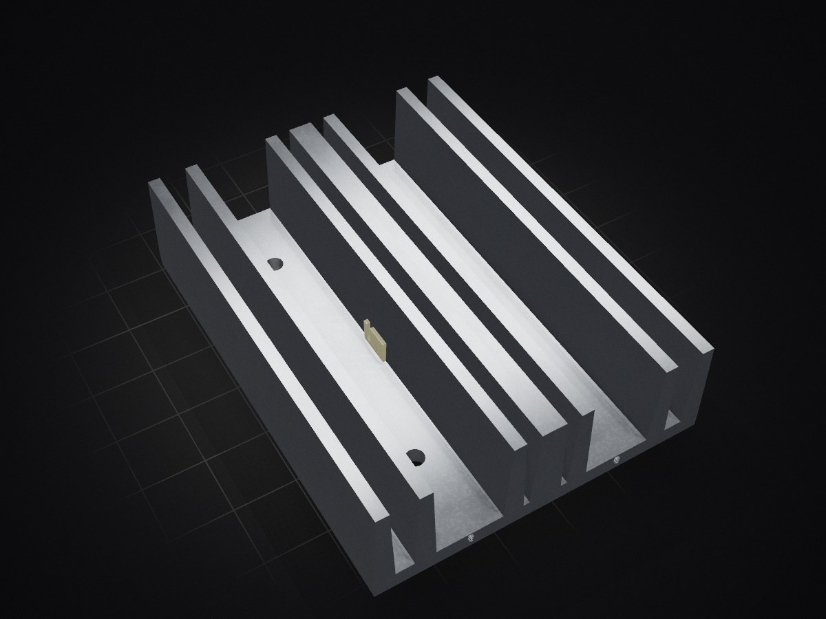
 01binary/str1ker20
A human-scale mech integrated with Robot Operating System
ArmEncoderBoard is an open-source printed circuit board by 01binary, from the 01binary/str1ker repository on GitHub. It is a 2-layer board of 34 × 34 mm with 34 parts on 27 nets, routed with 145 tracks and 10 vias.
It is built around the SN74LVC2G17DBVR, BAT54 and SS8050. Its parts include 13 resistors, 5 capacitors, 4 diodes, 2 ICs and 2 transistors.


A board that controls the mobile platform with four mecanum wheels:
The following components are placed onto the board as modules:
| Module | Function |
|---|---|
| Teensy 4.1 | ROS Node |
| Adafruit 9-DOF IMU | TF2 Transform |
The following external components are connected to the board via JST-XH locking connectors:
| Device | Function |
|---|---|
| 8x IBT2 Motor Drivers | Wheel Motor Drivers, Leg Actuator Drivers (8 pin IDC connector: 3V3, GND, L_EN, R_EN, LPWM, RPWM, L_IS, R_IS) |
| 4x Feedback Rod Linear Actuator Potentiometers | Leg Actuator Potentiometers (3 pin JST-XH connector: 3V3, SIG, GND) |
| 4x Leg (Wheel) Encoder Board | Wheel Encoders (8 pin IDC connector: A, B, I, 3V3, and four GND's |
There are four legs and each has two motors: a linear lift actuator and a brushed DC motor that runs the wheel.
Each PWM channel gets its own EN (Enabled) signal. The current sense signals (L_IS, R_IS) are included in the connector layout and sent over the wire, but not used anywhere on the board because there aren't enough pins for them. A multiplexer can be added later if the signals are desired.
The linear lift actuators have built-in multi-turn potentiometers. These are routed to Teensy ADC pins.
The wheel encoders are connected to each of the four wheels, outputting A, B, and I pulses counting rotations (1000 pulses per revolution).
Four 7-segment common anode LED number displays with decimal points display the speed of each wheel from 0.0 to 1.0. They are driven by an LED multiplexer.
The LED multiplexer is mapped to four 2-digit LED displays with decimal point as follows:
| Display function | IS31FL3730 pins |
|---|---|
| Digit common anodes | SW1–SW8 |
| Segments A, B, C, D, E, F, G, DP | CS1–CS8 |
The 3621BH common-anode LED displays have the following pin footprint:
| 1 | 2 | 3 | 4 | 5 | |
|---|---|---|---|---|---|
| 1 | COM0 | B | C | E | D |
| 2 | G | DP | A | F | COM1 |
The digit segments are mapped as follows:
| Digit | Segments |
|---|---|
 | A - Top of upper squareF - Left of upper squareB - Right of upper squareG - Link of both squaresE - Left of lower squareC - Right of lower squareD - Bottom of lower squareDP - Decimal point |
This board is essentially a shield. Labeled locking connectors are provided for all of the devices, PWM enabled/activity is indicated by LEDs, and wheel speeds are indicated by number displays.
| Pin | Function | Group |
|---|---|---|
A16 | Actuator 1 Potentiometer SIG | Front Left Leg (Actuator) |
D32 | Quadrature Encoder 1 A | Front Left Leg (Wheel) |
D33 | Quadrature Encoder 1 B | Front Left Leg (Wheel) |
D22 | Quadrature Encoder 1 Index | Front Left Leg (Wheel) |
D26 | Motor Driver 1 EN | Front Left Leg (Wheel) |
D27 | Motor Driver 2 EN | Front Left Leg (Actuator) |
D0 | Motor Driver 1 RPWM | Front Left Leg (Wheel) |
D1 | Motor Driver 1 LPWM | Front Left Leg (Wheel) |
D2 | Motor Driver 2 RPWM | Front Left Leg (Actuator) |
D3 | Motor Driver 2 LPWM | Front Left Leg (Actuator) |
A17 | Actuator 2 Potentiometer SIG | Front Right Leg (Actuator) |
D34 | Quadrature Encoder 2 A | Front Right Leg (Wheel) |
D35 | Quadrature Encoder 2 B | Front Right Leg (Wheel) |
D23 | Quadrature Encoder 2 Index | Front Right Leg (Wheel) |
D28 | Motor Driver 3 EN | Front Right Leg (Wheel) |
D29 | Motor Driver 4 EN | Front Right Leg (Actuator) |
D4 | Motor Driver 3 RPWM | Front Right Leg (Wheel) |
D5 | Motor Driver 3 LPWM | Front Right Leg (Wheel) |
D6 | Motor Driver 4 RPWM | Front Right Leg (Actuator) |
D7 | Motor Driver 4 LPWM | Front Right Leg (Actuator) |
A2 | Actuator 3 Potentiometer SIG | Rear Left Leg (Actuator) |
D36 | Quadrature Encoder 3 A | Rear Left Leg (Wheel) |
D37 | Quadrature Encoder 3 B | Rear Left Leg (Wheel) |
D24 | Quadrature Encoder 3 Index | Rear Left Leg (Wheel) |
D30 | Motor Driver 5 EN | Rear Left Leg (Wheel) |
D31 | Motor Driver 6 EN | Rear Left Leg (Actuator) |
D8 | Motor Driver 5 RPWM | Rear Left Leg (Wheel) |
D9 | Motor Driver 5 LPWM | Rear Left Leg (Wheel) |
D10 | Motor Driver 6 RPWM | Rear Left Leg (Actuator) |
D11 | Motor Driver 6 LPWM | Rear Left Leg (Actuator) |
A3 | Actuator 4 Potentiometer SIG | Rear Right Leg (Actuator) |
D38 | Quadrature Encoder 4 A | Rear Right Leg (Wheel) |
D39 | Quadrature Encoder 4 B | Rear Right Leg (Wheel) |
D25 | Quadrature Encoder 4 Index | Rear Right Leg (Wheel) |
D20 | Motor Driver 7 EN | Rear Right Leg (Wheel) |
D21 | Motor Driver 8 EN | Rear Right Leg (Actuator) |
D12 | Motor Driver 7 RPWM | Rear Right Leg (Wheel) |
D13 | Motor Driver 7 LPWM | Rear Right Leg (Wheel) |
D14 | Motor Driver 8 RPWM | Rear Right Leg (Actuator) |
D15 | Motor Driver 8 LPWM | Rear Right Leg (Actuator) |
A5 | I2C SCL | IMU, LED Driver |
A4 | I2C SDA | IMU, LED Driver |
| Device | Bus | Address |
|---|---|---|
| IMU | I2C | 0x28 (ADR tied to GND to set address) |
| IS31FL3730 | I2C | 0x74 |
| Component | Description |
|---|---|
| IS31FL3730 | LED Driver/Multiplexer |
| CL3621BH | LED Displays (2-Digit, 7-Segment, 10-Pin Common Anode) for Wheel Speeds |
| XL-1608SURC-06 | Red LED for EN signals |
| 150080BS75000 | Blue LED for LPWM/RPWM signals |
| RC0603FR-07150RL | 150 Ohm LED Resistor |
| RC0603FR-07470RL | 470R Red LED Resistor |
| RCG06031K00FKEA | 1K LED Resistor |
| RC0603FR-072K2L | 2.2K Series Resistor (ADC channels) |
| CR0603-FX-4701ELF | 4.7K Pull-Up Resistor for LED Multiplexer |
| CRCW060310K0FKEA | 10K 555 Timer Pull-Up Resistor, Transistor Base Resistor |
| HoAR0603-1/10W-20KR-1%-TCR25 | 20K LED Driver Current Setting Resistor |
| CRCW0603100KFKEA | 100K Transistor Base Pull-Down Resistor |
| RC0603FR-07360KL | 360K 555 Timer Resistor |
| C0402C103J4RACTU | 10nF 555 Timer Capacitor |
| CL10B473KB8NNNC | 47nF Decoupling Capacitor (ADC channels) |
| CC0603KRX7R9BB104 | 100nF IMU Capacitor |
| CC0603JRX7R7BB105 | 1uF 555 Timer Capacitor |
| SN74HC08DR | IC Gate |
| MMBT3904LT1G | LED Transistor |
| TLC555CDR | 555 Timer |
| JST_XH_B3B-XH-A | Actuator Potentiometers (3V3, SIG, GND) |
| Molex 0702460802 | Motor Drivers (LPWM, RPWM, L_EN, R_EN, L_IS, R_IS, 3V3, GND) |
| Teensy 4.1 | Teensy 4.1 without Headers |
| ICM-648-1-GT-HT | Teensy IC DIP Socket, 48P |
| Needle Headers | Teensy Needle Headers for DIP Socket |
| DIP Socket 10 pin | LED number displays IC socket |
| Qty | Value | Footprint | References |
|---|---|---|---|
| 4 | MountingHole | MountingHole:MountingHole_3.5mm_Pad | H1, H2, H3, H4 |
| 3 | 100K | Resistor100K:CRCW0603100KFKEA | R6, R7, R9 |
| 3 | 1K | Resistor1K:RCG06031K00FKEA | R4, R12, R13 |
| 3 | BAT54 | EnvelopeDiode:BAT54WS-7-F | CR1, CR2, CR3 |
| 3 | LEDRED | LedRed:NCD0603R1 | D2, D3, D4 |
| 2 | 100nF | Capacitor100nF:CC0603KRX7R9BB104 | C1, C2 |
| 2 | 10K | Resistor10K:CRCW060310K0FKEA | R10, R11 |
| 2 | 1uF | Capacitor1uF:CC0603JRX7R7BB105-L | C3, C4 |
| 2 | 4.7K | Resistor4.7K:CR0603-FX-4701ELF | R1, R2 |
| 2 | 47K | Resistor47K:RC0603FR-0747KL | R5, R8 |
| 2 | SS8050 | Package_TO_SOT_SMD:SOT-23 | Q1, Q2 |
| 1 | 10nF | Capacitor10nF:GRM1885C1H103JA01D | C5 |
| 1 | 150R | Resistor150:RESC1607X60N | R3 |
| 1 | AS5045B | Package_SO:SSOP-16_5.3x6.2mm_P0.65mm | U2 |
| 1 | Conn_01x05 | Connector_JST:JST_XH_B5B-XH-A_1x05_P2.50mm_Vertical | J1 |
| 1 | LEDBLUE | LedBlue:150080BS75000_Modified | D1 |
| 1 | SN74LVC2G17DBVR | SchmittBuffer:SN74LVC2G17DBVR | U1 |
It measures 34 × 34 mm and has 2 copper layers, 1.6 mm thick.
34 parts, built around the SN74LVC2G17DBVR, BAT54 and SS8050. The full list of its parts is on this page, with links to each part's symbol and footprint where PCBKit's library has them.
From the 01binary/str1ker repository on GitHub, at the commit this page was made from: the board is boards/ArmEncoderBoard/ArmEncoderBoard.kicad_pcb and its schematic boards/ArmEncoderBoard/ArmEncoderBoard.kicad_sch. PCBKit opens the board in the browser, with nothing to install.
Its repository states no licence, so its author keeps all rights: ask 01binary before reusing the design.
01binary/str1ker
A human-scale mech integrated with Robot Operating System

01binary/str1ker
A human-scale mech integrated with Robot Operating System

01binary/str1ker
A human-scale mech integrated with Robot Operating System


paltatech/current_sensor
Isolated delta sigma current sensor for high speed high current application

Bogdan8266/h616-board
8-layer Allwinner H616/618 SBC with DDR3, USB, Wi-Fi/BT and battery power support, designed for embedded Linux.

11philip22/tang-usb-ls-sniffer
A KiCad USB sniffer HAT for the Tang Nano 9K, designed to decode characters from compatible 1.5 Mb/s low-speed USB keyboards on the FPGA and send them over UART.


DsThakurRawat/PCB-AND-CHIP-DESIGN-WITH-AIML
All production files have been generated in manufacturing/: - Gerber Layers (RS-274X): Copper, solder masks, silkscreen, and board edge cuts (manufacturing/gerbers/) - Excellon Drill Files: Plated and non-plated drill…

ECE49022Team22/delivery-robot-pcb
Delivery robot KiCad PCB project and reusable 3.3 V LDO module
