


2 layers230 × 230 mm

 znuh/exposure-notifications
Visualizer for Covid-19 Exposure Notifications
Matrixctl is an open-source printed circuit board by znuh, from the znuh/exposure-notifications repository on GitHub. It is a 2-layer board of 66.8 × 29.7 mm with 31 parts on 50 nets, routed with 315 tracks and 137 vias.
It is built around the AP3428WT, BAT60A and MICROSMD050F-2. Its parts include 9 resistors, 8 capacitors, 5 connectors, 3 ICs and 1 diode.
Printed Circuit Boards for the Covid-19 Exposure Notifications Visualizer - see this for more details
To remake Exposure Notifications you need to get/make four things:
The printed circuit board designs are made with a Nightly Development Build of KiCAD. If you want to open/edit them you also need a recent Nightly Development Build. If you just want to use the PCBs unmodified you can also use the gerber-files from the gerber-subdirectories.
The LED matrix board uses Würth 150141RV73100 LEDs. These are bicolor-LEDs but only the red LED is used.
The landing pads for the LEDs have been reduced to a minimum to hide the pads underneath the LEDs. All PCB tracks are on the back side of the PCB. 1206 0-Ohms resistors are used instead of vias to cross tracks.
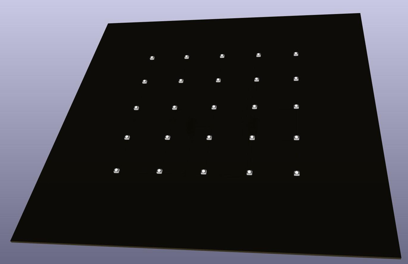
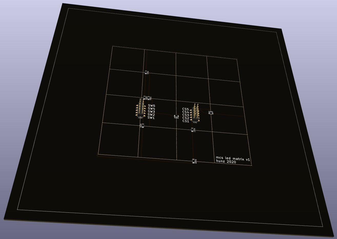
The part number of the micro:bit socket is PIS-1240. The Micro-USB connector is a Molex 105017-0001. You can get these parts and all additional components from digi-key.
Following a recommendation from the IS31FL3738 datasheet the board includes a Tantalum Capacitor to avoid audible noise produced by ceramics capacitors through the piezoelectric effect. Tantalum is a conflict resource. I've chosen a Kemet T495B336K010ATE450 because Kemet is a sane choice in general and their handling of the issue sounds ok.
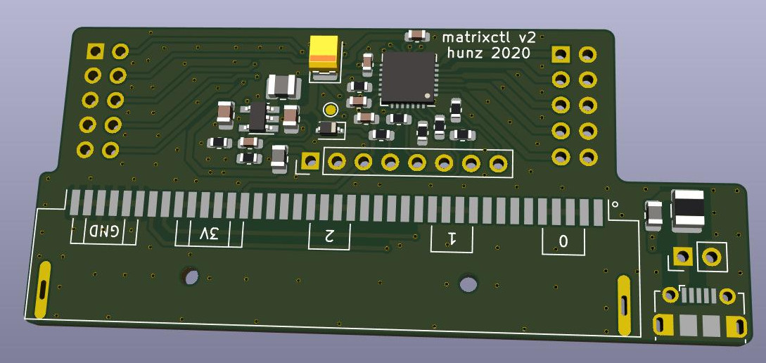 If you do not want to use the micro:bit socket you can also connect the micro:bit or a Calliope Mini to the pin header of the PCB. You need to connect I²C (SCL and SDA), 3V and GND.
| Qty | Value | Footprint | References |
|---|---|---|---|
| 4 | 1u | Capacitor_SMD:C_0603_1608Metric | C102, C103, C104, C105 |
| 3 | 2.2k | Resistor_SMD:R_0603_1608Metric | R103, R104, R112 |
| 2 | 10u | Capacitor_SMD:C_0805_2012Metric | C1, C3 |
| 2 | 600R/1A/0.1 | Inductor_SMD:L_0805_2012Metric | FB101, FB102 |
| 2 | Conn_02x05_Odd_Even | Connector_PinSocket_2.54mm:PinSocket_2x05_P2.54mm_Vertical | J101, J102 |
| 1 | 0 | Resistor_SMD:R_0603_1608Metric | R106 |
| 1 | 100k | Resistor_SMD:R_0603_1608Metric | R101 |
| 1 | 120k | Resistor_SMD:R_0603_1608Metric | R2 |
| 1 | 20k | Resistor_SMD:R_0603_1608Metric | R105 |
| 1 | 22p | Capacitor_SMD:C_0603_1608Metric | C2 |
| 1 | 2u2 | Inductor_SMD:L_1008_2520Metric | L1 |
| 1 | 33u/10V | Capacitor_Tantalum_SMD:CP_EIA-3528-21_Kemet-B | C101 |
| 1 | 442k | Resistor_SMD:R_0603_1608Metric | R1 |
| 1 | AP3428 | Package_TO_SOT_SMD:TSOT-23-5 | U1 |
| 1 | BAT60A | Diode_SMD:D_SOD-323 | D101 |
| 1 | Conn_01x02 | Connector_PinHeader_2.54mm:PinHeader_1x02_P2.54mm_Vertical | J1 |
| 1 | Conn_01x08 | Connector_PinHeader_2.54mm:PinHeader_1x08_P2.54mm_Vertical | J103 |
| 1 | DNP | Resistor_SMD:R_0603_1608Metric | R102 |
| 1 | IS31FL3738 | matrixctl:QFN-28-1EP_5x5mm_P0.5mm_EP3.5x3.5mm_ThermalVias | U101 |
| 1 | MICROSMD050F-2 | Fuse:Fuse_1210_3225Metric | F1 |
| 1 | TestPoint | TestPoint:TestPoint_Pad_D1.0mm | TP101 |
| 1 | USB_B_Micro | Connector_USB:USB_Micro-B_Molex-105017-0001 | J104 |
| 1 | bbc_microbit | matrixctl:PIS-1240 | U2 |


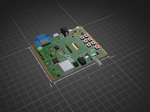
M17-Project/Module_17
M17 modem board for 9600-baud capable radios


crgarcia12/electronics-homeassistant-lightscontroll
A smart lighting controller PCB that integrates seamlessly with ESPHome and Home Assistant while maintaining full compatibility with traditional mechanical switches.


It measures 66.8 × 29.7 mm and has 2 copper layers, 1.6 mm thick.
31 parts, built around the AP3428WT, BAT60A and MICROSMD050F-2. The full list of its parts is on this page, with links to each part's symbol and footprint where PCBKit's library has them.
From the znuh/exposure-notifications repository on GitHub, at the commit this page was made from: the board is matrixctl-v2/matrixctl.kicad_pcb and its schematic leds/leds.kicad_sch. PCBKit opens the board in the browser, with nothing to install.
Its repository states no licence, so its author keeps all rights: ask znuh before reusing the design.
