
4 layers60 × 127 mm

 M17-Project/M17_331068
Mainboard replacement for Nokia 3310
M17 3310 is an open-source printed circuit board by M17-Project, from the M17-Project/M17_3310 repository on GitHub. It is a 4-layer board of 41.4 × 108 mm with 124 parts on 105 nets, routed with 702 tracks and 433 vias.
It is built around the LFCN-490+, TPS63031DSK and USBLC6-2SC6, with the BAT60A, BSS138 and IRLML6401 among its other parts. Its parts include 35 resistors, 22 capacitors, 17 switches, 13 diodes and 8 connectors. It belongs with the STM32 boards of this library.


Mainboard replacement for the Nokia 3310/3330.
[!CAUTION] The board's thickness is 1.0mm. Anything thicker will not fit.
Both photos in the misc directory are cropped, so that if you scale them for 108mm height, you should be able to make direct measurements using GIMP or other image editing software.
An interactive HTML version of the Bill of Materials can be found here.
The RF module must be flashed with OpenRTX. It can be flashed before or after soldering it in place as the PCB has a hole through which the four programming pads are still accessible.
First of all, download and install the rl78flash utility. How you install it, depends on your operating system.
Now download the latest OpenRTX firmware for the SA868S UHF module. Here is an example for version 1.4.1:
# cd ~/Downloads
# wget https://github.com/OpenRTX/sa8x8-fw/releases/download/v1.4.1/sa8x8-fw-sa868s-uhf.s37
We now have the software and firmware in place but we need to build a small programming adapter. You can build one with a UART to USB converter, two 1N5819 diodes, some wire and a small PCB. Here's a diagram showing how it is connected:
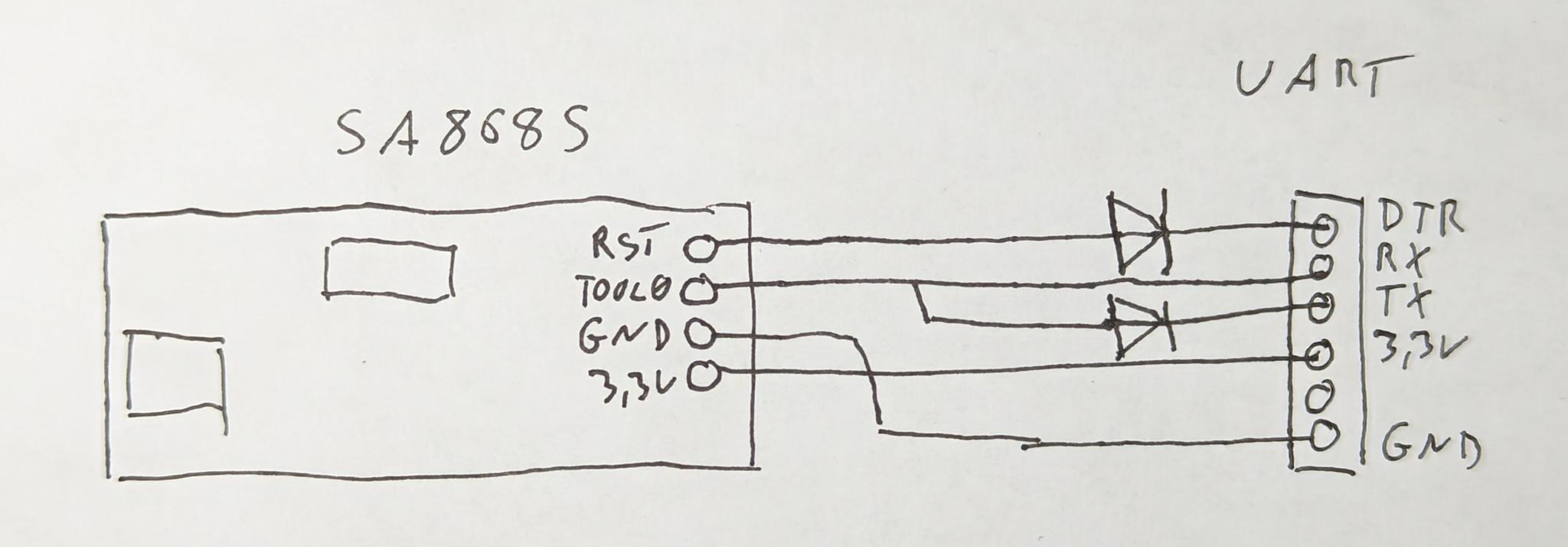
Here is how it could look like:
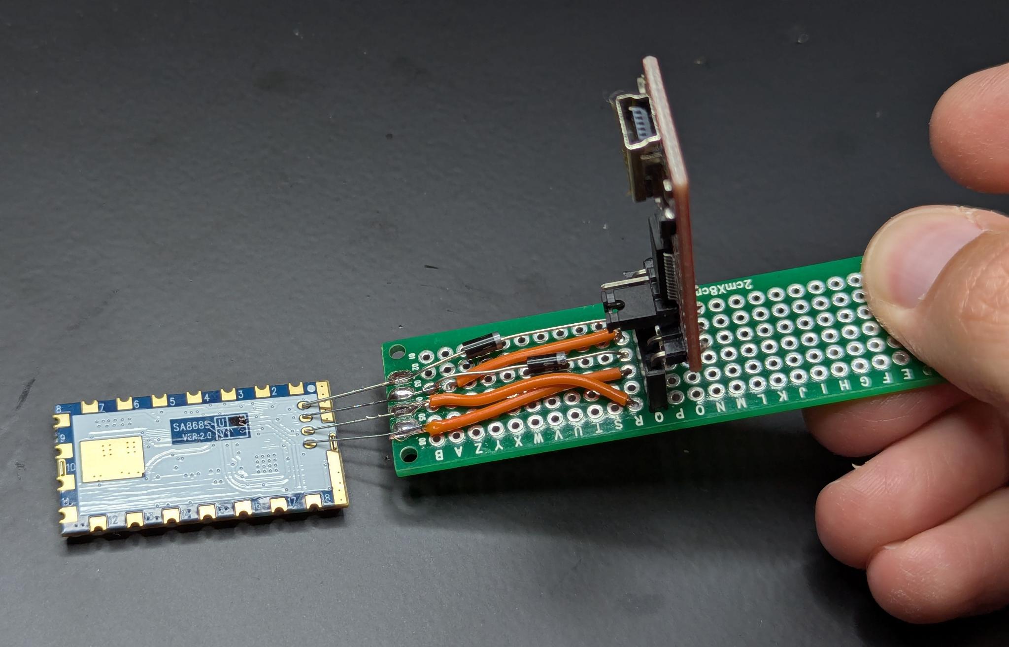
For the four pins, cut and solder the legs of a few resistors to the front of the PCB and bend them to the spacing of the four pins of the SA868S. The rest is quite self-explainatory.
To flash the firmware, plug in the UART to USB converter, hold the board with the four pins to the SA868S module and execute the following command.
Note: Make sure to jumper the converter to 3.3V!
# cd ~/Downloads/rl78flash/
# flash % ./rl78flash -m 1 -a -v /dev/tty.usbserial-A50285BI ~/Downloads/sa8x8-fw-sa868s-uhf.s37
rl78flash v0.7.0
Protocol configuration: protocol=0, code_block=1024, data_block=1024
Erase code flash
Erase data flash
Read file "/Users/rz01/Downloads/sa8x8-fw-sa868s-uhf.s37"
Write code flash
Write data flash
Verify Code flash
Verify Data flash
Reset MCU
In this case, flash mode 1 (-m 1) was chosen as the UART to USB converter has a DTR pin. You might need to wire your adapter differently and then select another mode depending on your specific UART to USB board. Please consult this README and this diagram for more information on this.
[!NOTE] The device will appear frozen if the firmware running on the RF module is not OpenRTX.
See the example firmware here.
The device should enter USB DFU mode and should be recognized by CubeProgrammer.
| Qty | Value | Footprint | References |
|---|---|---|---|
| 14 | ~ | Parts:3310_key | SW3, SW4, SW5, SW6, SW7, SW8, SW9, SW10, SW11, SW12, SW13, SW14, SW15, SW17 |
| 11 | 47k | Resistor_SMD:R_0402_1005Metric | R3, R4, R9, R11, R12, R18, R31, R32, R33, R34, R35 |
| 9 | 100n | Capacitor_SMD:C_0402_1005Metric | C5, C6, C7, C8, C9, C10, C12, C13, C19 |
| 9 | 56R | Resistor_SMD:R_0402_1005Metric | R16, R19, R21, R22, R23, R24, R25, R26, R27 |
| 8 | RED | Parts:3310_led | D5, D6, D7, D9, D10, D11, D12, D13 |
| 7 | 100k | Resistor_SMD:R_0402_1005Metric | R7, R8, R10, R13, R15, R17, R20 |
| 7 | ~ | Parts:2mm_mounting_hole_sig | H1, H2, H3, H4, H5, H6, H7 |
| 5 | BAT60A | Diode_SMD:D_SOD-323 | D1, D2, D3, D4, D8 |
| 5 | BSS138 | Package_TO_SOT_SMD:SOT-23 | Q1, Q3, Q4, Q5, Q7 |
| 3 | 10uF/10V | Capacitor_Tantalum_SMD:CP_EIA-3528-21_Kemet-B | C14, C15, C16 |
| 3 | 47uF/10V | Capacitor_Tantalum_SMD:CP_EIA-3528-21_Kemet-B | C11, C17, C18 |
| 3 | Bead | Inductor_SMD:L_0805_2012Metric | FB1, FB2, FB3 |
| 2 | 1k | Resistor_SMD:R_0402_1005Metric | R14, R28 |
| 2 | 20p | Capacitor_SMD:C_0402_1005Metric | C21, C22 |
| 2 | 22k | Resistor_SMD:R_0402_1005Metric | R1, R6 |
| 2 | 2u2 | Capacitor_SMD:C_0402_1005Metric | C3, C4 |
| 2 | 5k1 | Resistor_SMD:R_0402_1005Metric | R29, R30 |
| 2 | 6p8 | Capacitor_SMD:C_0402_1005Metric | C1, C2 |
| 2 | IRLML6401 | Package_TO_SOT_SMD:SOT-23 | Q2, Q6 |
| 1 | "OK" | Parts:3310_key | SW2 |
| 1 | 10k | Resistor_SMD:R_0402_1005Metric | R5 |
| 1 | 10n | Capacitor_SMD:C_0402_1005Metric | C20 |
| 1 | 1u5 | Inductor_SMD:L_1210_3225Metric | L1 |
| 1 | 2k2 | Resistor_SMD:R_0402_1005Metric | R2 |
| 1 | 32.768kHz | Parts:xtal_smd_32k | Y2 |
| 1 | 8MHz | Crystal:Crystal_SMD_3225-4Pin_3.2x2.5mm | Y1 |
| 1 | ANT_A | TestPoint:TestPoint_Pad_D1.5mm | J2 |
| 1 | ANT_B | TestPoint:TestPoint_Pad_D1.5mm | J3 |
| 1 | Battery | Parts:3310_batt | J4 |
| 1 | Buzzer | Parts:3310_buzzer | J6 |
| 1 | Display | Parts:3310_display | J7 |
| 1 | LFCN-490+ | Filter:Filter_Mini-Circuits_FV1206 | FL1 |
| 1 | MAX1555 | Package_TO_SOT_SMD:TSOT-23-5 | U3 |
| 1 | MAX16054 | Package_TO_SOT_SMD:TSOT-23-6 | U4 |
| 1 | ML414H-IV01E | Parts:ML414H | BT1 |
| 1 | POWER ON/OFF | Parts:SIDE PUSH 2.2NF 4.7x3.2x1.65mm | SW1 |
| 1 | SA868 | Parts:SA868-VER1.1 | U2 |
| 1 | STM32F405RGTx | Package_QFP:LQFP-64_10x10mm_P0.5mm | U1 |
| 1 | SWD_DBG | Parts:3310_4_pin | J1 |
| 1 | TPS63031DSK | Package_SON:WSON-10-1EP_2.5x2.5mm_P0.5mm_EP1.2x2mm | U5 |
| 1 | USB C | Connector_USB:USB_C_Receptacle_GCT_USB4110 | J8 |
| 1 | USBLC6-2SC6 | Package_TO_SOT_SMD:SOT-23-6 | U6 |
| 1 | Vibrator | Parts:3310_vibrator | J5 |
| 1 | ~ | Parts:3310_key_gap | SW16 |
| 1 | ~ | Parts:3310_speaker | LS1 |


ceilingduster/kv4p-ht-dmr
Please see the main project site: https://kv4p.com. Thank you Vance for an incredible project! This MOD is only meant to serve to innovate and support the greater project.


polesskiy-dev/iot-risk-data-logger-nfc-samd21-hardware
Hardware (schematics, PCB, BOM) for iot-risk-data-logger-nfc-samd21 project

polesskiy-dev/iot-risk-logger-stm32l4
Open IoT risk data logger based on STM32L4 MCU


portapack-mayhem/mayhem-mdk
PortaPack - Module Develoment Kit
It measures 41.4 × 108 mm and has 4 copper layers, 0.98 mm thick.
124 parts, built around the LFCN-490+, TPS63031DSK, USBLC6-2SC6 and BAT60A. The full list of its parts is on this page, with links to each part's symbol and footprint where PCBKit's library has them.
From the M17-Project/M17_3310 repository on GitHub, at the commit this page was made from: the board is M17_3310.kicad_pcb and its schematic M17_3310.kicad_sch. PCBKit opens the board in the browser, with nothing to install.
Its repository states no licence, so its author keeps all rights: ask M17-Project before reusing the design.