DroneBMS is an open-source printed circuit board by zmuhammad07, from the zmuhammad07/TakeUp repository on GitHub, published under the MIT licence. It is a 4-layer board of 90 × 51 mm with 42 parts on 11 nets, routed with 139 tracks and 156 vias.
It is built around the AMS1117-3.3 and SMAJ15A. Its parts include 13 capacitors, 6 resistors, 3 diodes, 2 ICs and 2 connectors.
TakeUp is a custom quadrotor flight stack built from scratch: a hand-wired STM32F4 flight controller, a self-etched power distribution board, a bit-banged NRF24L01+ radio link, and a from-scratch DShot150 ESC driver. The end goal is voice-controlled flight — commands transmitted over audio instead of a stick input — with the current build flying on a manual PS5-controller-over-RF link while the audio pipeline is developed.
Status: in progress. Attitude estimation, the RF link, and standard PWM motor control are working. DShot150 and voice control are active work-in-progress (see Known Limitations).
Today, the RC packet source is a PS5 controller relayed through an ESP32 (Software/Src/esp32.c) rather than voice — this is the interim control path used to validate the flight controller, IMU fusion, and radio link while the voice front-end is built out.
The flight controller runs on an STM32F4 Nucleo-64 board (pin map matches the standard Nucleo layout: PC13 user button, PA5 = LD2). Firmware is generated with STM32CubeMX/HAL and hand-extended.
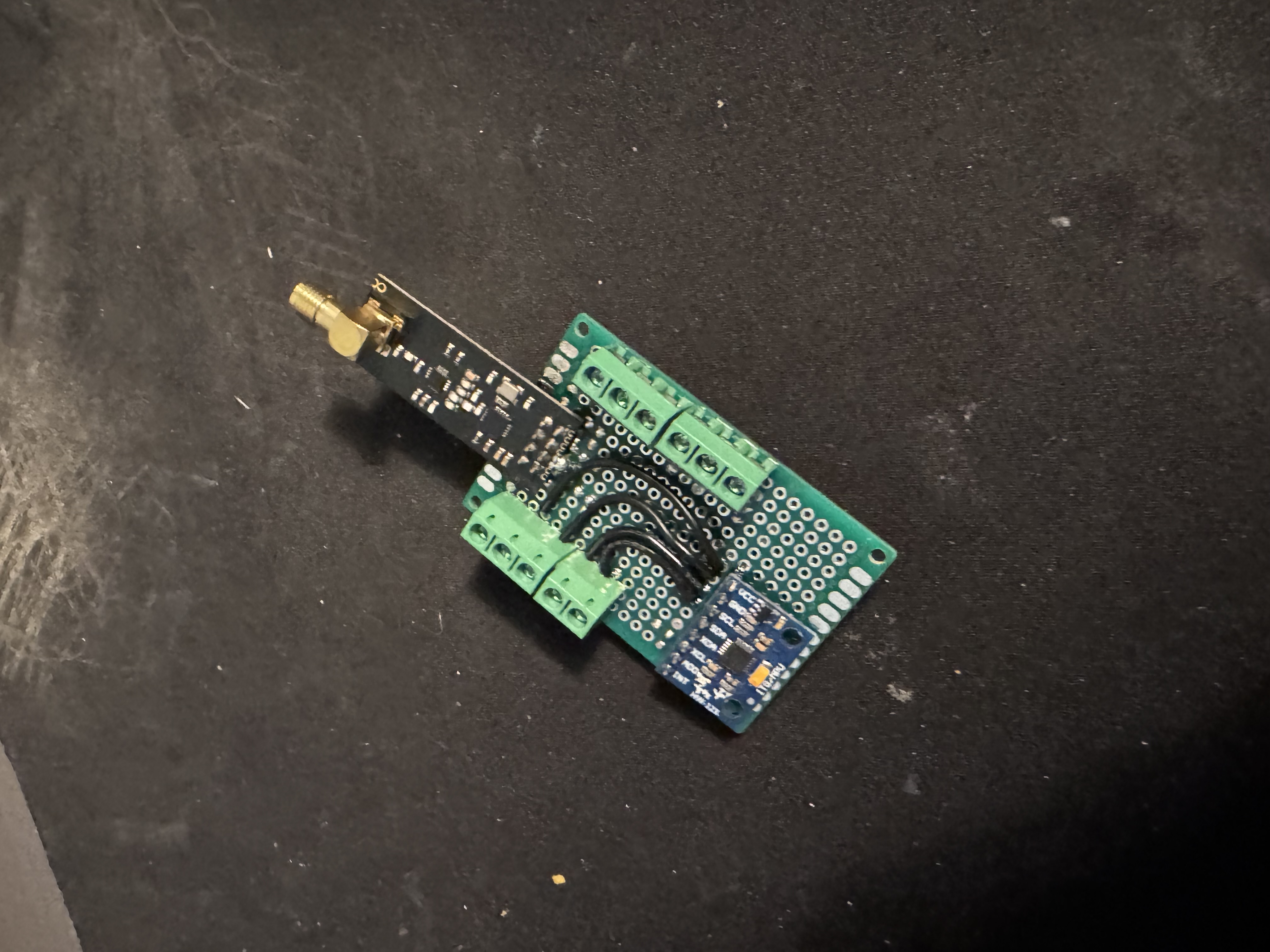
Hand-wired prototype: MPU6050 breakout and NRF24L01+ (with SMA antenna) soldered onto perfboard with screw-terminal breakouts for power and signal.
Boot sequence (main.c): GPIO → USART2 → I2C1 → SPI2 → TIM2 → arm ESC (Motor_Init) → bring up radio (Nrf_init) → enter RX loop, printing BOOT/I2C OK/SPI OK/TIM OK over UART at each stage so a bring-up failure is localized immediately from the serial log.
IMU / Attitude Estimation (MPU6050)
mpu6050.c talks to the MPU6050 directly over I2C1 (no external library) at address 0x68.
Init sequence:
Register
Value
Purpose
0x75 (WHO_AM_I)
read, expect 0x68
sanity check on boot
0x6B (PWR_MGMT_1)
0x00
wake from sleep, select internal clock
0x1A (CONFIG)
0x01
DLPF on, ~184 Hz bandwidth
0x25 (SMPLRT_DIV)
0x00
sample rate = 1 kHz / (1 + 0) = 1 kHz
0x1B (GYRO_CONFIG)
0b00011000
±2000 °/s full scale
0x1C (ACCEL_CONFIG)
0x00
±16 g full scale
Raw accel/gyro burst-reads come from 0x3B (6 bytes, accel X/Y/Z) and 0x43 (6 bytes, gyro X/Y/Z), scaled by the datasheet sensitivity for the selected range (/16384.0f g/LSB for accel, /16.4f (°/s)/LSB for gyro).
Gyro calibration (calibrate_gyro) averages 1000 samples at boot to compute a static bias — currently computed but not yet subtracted from live readings (see Known Limitations).
Attitude fusion (log_data) runs a single-stage complementary filter:
Exponential low-pass (ALPHA = 0.02) on both accel and gyro channels.
Gyro integration at dt = 0.001 s (1 kHz loop assumption) added to the running angle.
Fusion with accel-derived tilt (atan/asin off the gravity vector) at a 0.98 / 0.05 gyro/accel blend, printed over USART2 as Pitch:__, Roll:__.
Wireless Link (NRF24L01+)
Both ends of the radio link are custom drivers — the STM32 side (Nrf2401.c) talks directly to the NRF24L01+ command/register set over SPI2 with no radio library, and the transmit side (esp32.c) uses the Arduino RF24 library on an ESP32 paired to a PS5 controller over Bluetooth.
Link configuration (must match on both ends):
Setting
Value
Data rate
1 Mbps
RF channel
85 (2.485 GHz)
TX power
0 dBm
Address width
5 bytes (SETUP_AW = 0x03)
RX/TX address
E7 E7 E7 E7 E7
Payload size
16 bytes, static (no dynamic payloads)
Auto-ACK
disabled on both ends
CRC
16-bit (ESP32 side); STM32 driver disables hardware auto-ack/CRC handling and relies on the fixed packet contract instead
Packet format — a flat 16-byte struct sent as raw bytes:
TX side (esp32.c): reads PS5 gamepad stick axes via ps5Controller, maps left stick → throttle/roll and right stick → pitch/yaw, and pushes a packet over RF24::write() roughly every 20 ms.
RX side (Nrf2401.c + main.c): Nrf_init() powers up the radio, configures the RF settings above, and starts listening (CE high). Recieve_nrf() polls the STATUS register for the RX_DR flag, pulls the 16-byte payload with the R_RX_PAYLOAD command, and clears the flag. main.c copies the payload into an rc_packet, runs the throttle channel through a first-order low-pass (alpha = 0.1), and feeds the result to Motor_SetSpeed().
Note: enable_auto_ack() exists in the driver but is not currently called from Nrf_init() — auto-ack stays disabled to match the transmitter's setAutoAck(false).
Motor Control
Motors.c drives ESCs with standard hobby PWM on TIM2 channel 1: with the timer clocked at 1 MHz (72 MHz / (prescaler 71 + 1)) and a 20000-tick period, CCR1 directly represents the pulse width in microseconds at a 50 Hz refresh rate — the same 1000–2000 µs framing every analog PWM ESC expects.
Function
Behavior
Motor_Init()
Arms the ESC: full throttle (2000) for 2 s, then minimum (1000) for 2 s, matching the standard ESC calibration/arm beep sequence
Motor_SetSpeed(percent)
Maps 0–100 % linearly to 1000–2000 µs
Motor_SetRaw(ccr)
Direct CCR write for bench testing
Motor_Stop()
Forces minimum throttle (1000)
Motor_Control_UART()
Serial bench-test command parser (S<pct> set speed, R<ccr> set raw, X stop) over USART2
Only TIM2_CH1 is currently wired to a motor output in main.c — channels 2–4 are configured (see pin table above) but not yet driven, so multi-motor mixing isn't implemented yet.
Custom DShot150 Driver
Dshot150.c implements the DShot150 digital ESC protocol frame-by-frame, from scratch, on top of TIM2 + DMA.
Frame construction is spec-correct. A DShot frame is 16 bits: 11-bit throttle value, 1 telemetry-request bit, and a 4-bit CRC:
Bit encoding. Each of the 16 frame bits is expanded into a duty-cycle value for one PWM period — 170 (≈85% duty) for a 1 bit, 85 (≈42.5% duty) for a 0 bit — into a 17-entry buffer (16 bits + a trailing 0 to force the line low/reset). The buffer is streamed to TIM2_CH1's CCR1 register via HAL_TIM_PWM_Start_DMA, so each bit's duty cycle loads automatically without CPU intervention.
Current state: this correctly reproduces DShot's bit encoding and checksum, but the timer feeding it is still configured for the 20 ms / 1 MHz standard-PWM setup described above rather than a proper DShot150 bit clock (real DShot150 needs a ~6.67 µs bit period, i.e. the whole 16-bit frame takes ~107 µs — not 16 × 20 ms). Getting this fully protocol-compliant means giving TIM2 a dedicated ARR/prescaler for DShot bit timing (or moving DShot to its own timer) and reworking the DMA burst length accordingly. This is the main piece marked "in progress" in this repo — see below.
Power Distribution Board
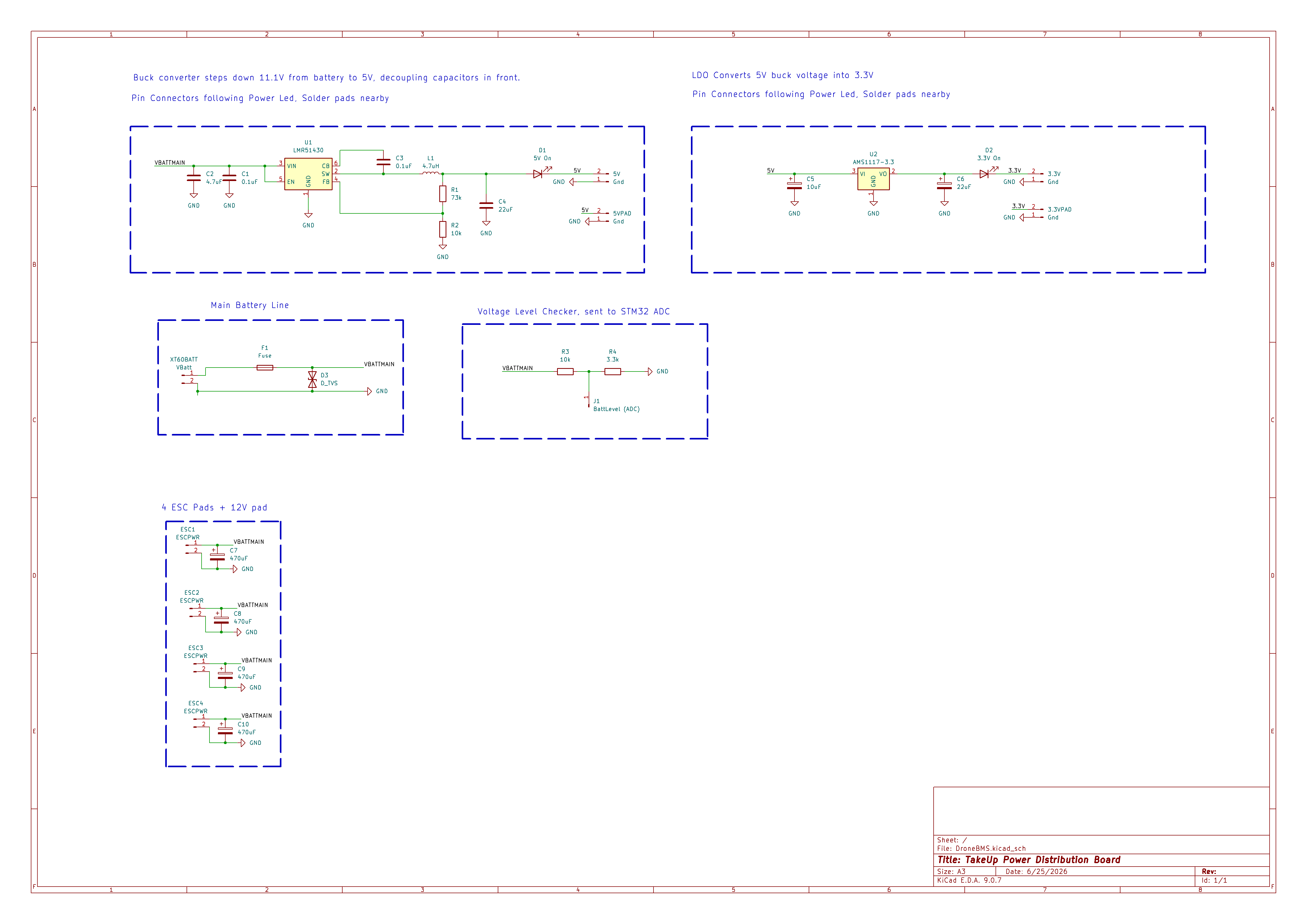
Hardware/BMS/DroneBMS.kicad_sch — titled "TakeUp Power Distribution Board" in the schematic sheet — is a custom 4-layer (1.6 mm) PCB that takes a 3S LiPo in over an XT60 connector and produces the regulated rails and battery telemetry the flight controller needs. It's referred to informally as the "BMS" but its scope today is power conditioning + voltage sensing rather than active cell balancing.
Scales VBATTMAIN down into ADC range for the STM32 to read pack voltage in software
ESC power
ESC1–ESC4 pads, 470 µF bulk cap each, plus a raw +12V pad
Distributes unregulated battery voltage directly to each ESC
Board: 4 copper layers (F.Cu/In1.Cu/In2.Cu/B.Cu), 1.6 mm stack-up, 4 mounting holes, KiCad 9 source files included for both schematic and layout, plus a 3D render at Hardware/BMS/PCB_Render_1.png.
Building the Firmware
The Software/ tree is a standard STM32CubeIDE / STM32CubeMX HAL project targeting an STM32F4 Nucleo-64 board.
Import Software/ into STM32CubeIDE (or point a Makefile-based ARM GCC toolchain at Software/INC and Software/Src).
Flash over the Nucleo's onboard ST-LINK.
Open a serial terminal at 115200 8N1 on the ST-LINK VCP to watch boot status (BOOT, I2C OK, SPI OK, TIM OK) and the live RC/attitude log.
Flash Software/Src/esp32.c to an ESP32 (Arduino core, RF24 + ps5Controller libraries) to act as the transmitter, or drive TIM2_CH1 directly via Motor_Control_UART() for a bench test with no radio at all.
Known Limitations / TODO
Voice control isn't implemented yet. The current transmit path is a PS5 controller relayed through an ESP32, standing in for the audio pipeline this project is ultimately meant to use.
Power board has no active cell balancing/protection IC — today it's fusing, a TVS clamp, regulation, and voltage-divider telemetry, not a full smart BMS.
It measures 90 × 51 mm and has 4 copper layers, 1.6 mm thick.
What parts does the DroneBMS use?
42 parts, built around the AMS1117-3.3 and SMAJ15A. The full list of its parts is on this page, with links to each part's symbol and footprint where PCBKit's library has them.
Where can I download the DroneBMS KiCad files?
From the zmuhammad07/TakeUp repository on GitHub, at the commit this page was made from: the board is Hardware/BMS/DroneBMS.kicad_pcb and its schematic Hardware/BMS/DroneBMS.kicad_sch. PCBKit opens the board in the browser, with nothing to install.
Can I use the DroneBMS design in my own project?
Its repository publishes it under the MIT licence: you may reuse it on that licence's terms (keep the author's notice, and for a copyleft licence share your changes alike).
A central brain running on teensy or a lighter MCU to process any control signals (MIDI, CV, our own) into the same but adding logic, ADSRs, DCOs, CV matrices etc. to it
A custom research-oriented battery interface and telemetry board for the DJI Spark platform, built around a standard 3S LiPo battery pack instead of the discontinued, hard-to-find OEM Smart Battery.
This is the repository for SALMO, the Solar Azimuth and eLevation Motorized lOcator. It is a PCB used for driving a tracking solar panel system, using GPS location and a MPPT algorithm to maximise the incident power.