4 layers85.7 × 73.9 mm

 thomasnonis/ppse-20215
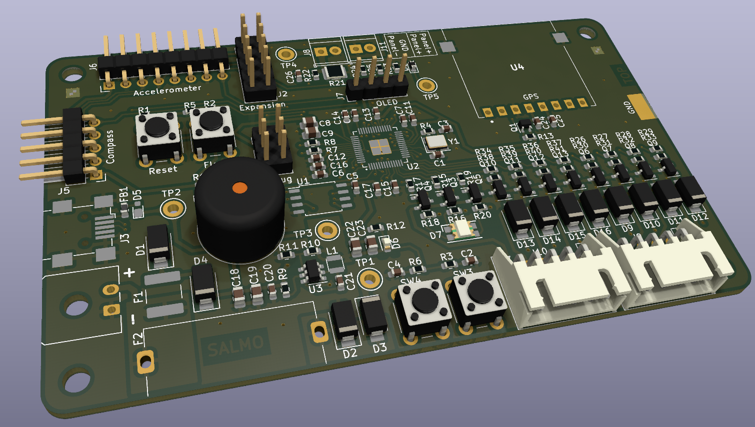
This is the repository for SALMO, the Solar Azimuth and eLevation Motorized lOcator. It is a PCB used for driving a tracking solar panel system, using GPS location and a MPPT algorithm to maximise the incident power. The official name of the project is PPS2021_SUN_TRK
Ppse-2021 is an open-source printed circuit board by thomasnonis, from the thomasnonis/ppse-2021 repository on GitHub. It is a 2-layer board of 100 × 60 mm with 133 parts on 96 nets, routed with 875 tracks and 139 vias.
It is built around the RP2040, W25Q16JVSSIQ and TPS563201, with the CGRA4007-HF, SI2300DS and BC846A among its other parts. Its parts include 41 resistors, 26 capacitors, 16 diodes, 13 transistors and 11 connectors. It belongs with the RP2040 boards of this library.


This is the repository for SALMO, the Solar Azimuth and eLevation Motorized lOcator. It is a PCB used for driving a tracking solar panel system, using GPS location and a MPPT algorithm to maximise the incident power.
The official name of the project is PPS2021_SUN_TRK
During the second semester of the 2021/2022 A.Y. of their bachelor degree in Electronics Engineering, a group of students known as SALMO SOCIETY, developed a custom board to solve real world problems.
Nowadays, we are all aware about climate change and it's impact, so the SALMO SOCIETY decided in partecipate to the renewable energy run, in particular exploiting the energy obtained by a solar panel to drive a load.
The aim of the board it's to move the solar panel using two step motors (along z-y axis) facilitating the MPP (Maximum Power Point) reaching and, as consequence, delivering the maximum power to the load.
Using a GPS module, the board knows exactly where it is located around the globe; afterwards the position of the sun is computed with a specific algorithm based on astronomical calculations. Then, the spatial position of the panel is derived by the accelerometer and compass modules; lastly, the motor is moved in order to follow the exact position of the sun (given its azimuth and elevation).
📂 SALMO_pico_fw    -> Firmware
📂 datasheets       -> Datasheet of every component mounted on board
📂 kicad-project -> KiCad and gerber files Debian:
sudo apt install cmake gcc-arm-none-eabi libnewlib-arm-none-eabi build-essentialFedora:
sudo dnf install cmake
sudo dnf group install "C Development Tools and Libraries" "Development Tools"
sudo dnf install gcc-arm-linux-gnu \
arm-none-eabi-gcc-cs-c++ \
arm-none-eabi-gcc-cs \
arm-none-eabi-binutils \
arm-none-eabi-newlib
then:
git pull
git submodule update --init --recursive
now add to your shell profile (~/.bashrc or ~/.zshrc) the current directory (pico-sdk folder) as env variable:
export PICO_SDK_PATH=<path_to>/pico-sdk
Windows:
Follow this guide and you're good to go.
Finally, in order to compile:
cd SALMO_pico_fw
mkdir build
cd build
cmake ..
cd src
make -j4
After this process some binaries files will be created.
The suitable one is the .uf2 file, which is located into SALMO_pico_fw/build/src.
Now you can start the board in bootloader mode:
BOOTSEL buttonThen drag and drop the .uf2 file to RPI-RP2 mass storage device.
If you want to install picotool and easily flash when RP2040 is not in BOOTSEL mode, you need to follow these steps:
sudo apt install build-essential pkg-config libusb-1.0-0-devsudo dnf install libusb-devel libusb libusb1-devel systemd-devel
sudo rebootxcode-select --install
brew install libusb
brew link --overwrite libusbFor now Picotool doesn't seem to work on Windows, skip these steps and flash "manually" moving the .uf2 file.
After you have downloaded picotool you have to compile it:
cd picotool
mkdir build
cd build
cmake ..
make
Afterwards, you must give execution permissions to the scripts:
cd ../../SALMO_pico_fw/src
sudo chmod +x build.sh
sudo chmod +x flash.sh
sudo chmod +x build_and_flash.sh
If something on MacOS doesn't work use
sudo chown -R {username}:{workgroup} ppse-2021Then, you can simply navigate to SALMO_pico_fw/src/ and execute build.sh, flash.sh or build_and_flash.sh to respectively build, flash or build and flash the project. :nail_care:
graph TB
A[Peripherals initialization] -->B(Infinite loop)
    B --> C{Is go home btn pressed?}
    C -->|Yes| D(Go home) --> E
    C -->|No| E{Is tracking enable btn pressed?}
	E -->|Yes| E1(Enable or disable tracking mode) --> F
	F{Is update_motor_position_timer elapsed <br>and tracking mode on?}
	F -->|Yes| G(Update motor position) --> H
	F -->|No| H{Is gps timer elapsed?}
	E -->|No| H
	H -->|Yes| I(Read and parse GPS output) --> L
	H -->|No| L{Is update sun position timer elapsed?}
	L -->|Yes| M(Run algorithm to compute sun position based on GPS data) --> B
L -->|No| BIn this sections you can find some guidelines in order in order to contribute with out project
A good commit message should be preceded by a prefix, then a colon and then a brief and descriptive comment on the changes made.
All commits should be written in the present simple tense (eg. add file, modify this, edit that).
Commits may also include longer descriptions in the second argument of a commit message.
Following are the prefix conventions for this repository.
hw: for hardware (schematic, pcb, ...)fw: for firmwaresw: for software (interfaces on a pc and such)docs: for documentationnotes: for lecture noteschore: for general tasks (file management, moving stuff around, ...):x: git commit -m "Added some features to code"
:heavy_check_mark: git commit -m "fw: add uart implementation to gps driver"
All files must have no spaces and should be lowercase.
:x: Name of file.ext
:heavy_check_mark: name-of-file.ext
If you want to add a new driver or library please keep this tree structure
📦 SALMO_pico_fw
 ┣📜 CMakeLists.txt (Project cmake file)
 ┣ 📂 build
 ┣ 📂 src
 ┗ 📜 CMakeLists.txt (SALMO.C cmake file)
 ┣ 📂 your_lib
 ┃ ┗ 📂 your_lib docs
 ┃ ┗ 📜 CMakeLists.txt (lib cmake file)
 ┃ ┗ 📜 your_lib.c.
 ┃ ┗ 📜 your_lib.h
Every library needs some sort of documentation, and of course a cmake file!
| Qty | Value | Footprint | References |
|---|---|---|---|
| 17 | 100n | Capacitor_SMD:C_0603_1608Metric | C2, C4, C6, C10, C11, C12, C13, C14, C15, C16, C17, C20, C21, C24, C25, C26 +1 |
| 15 | 10k | Resistor_SMD:R_0603_1608Metric | R1, R3, R6, R9, R11, R13, R22, R30, R31, R32, R33, R38, R39, R40, R41 |
| 8 | 22 | Resistor_SMD:R_0603_1608Metric | R26, R27, R28, R29, R34, R35, R36, R37 |
| 8 | CGRA4007 | Diode_SMD:D_SMA | D9, D10, D11, D12, D13, D14, D15, D16 |
| 8 | SI2300DS | Package_TO_SOT_SMD:SOT-23 | Q6, Q7, Q8, Q9, Q10, Q11, Q12, Q13 |
| 5 | 33k | Resistor_SMD:R_0603_1608Metric | R10, R15, R17, R19, R24 |
| 5 | TestPoint | TestPoint:TestPoint_Keystone_5005-5009_Compact | TP1, TP2, TP3, TP4, TP5 |
| 4 | MountingHole | MountingHole:MountingHole_3.2mm_M3 | H1, H2, H3, H4 |
| 3 | 470R | Resistor_SMD:R_0603_1608Metric | R16, R18, R20 |
| 3 | BC846A | Package_TO_SOT_SMD:SOT-23 | Q3, Q4, Q5 |
| 3 | Fiducial | ppse_2021:Fiducial-ppse | FID1, FID2, FID3 |
| 2 | 10u | Capacitor_SMD:C_0805_2012Metric | C18, C19 |
| 2 | 18p | Capacitor_SMD:C_0603_1608Metric | C1, C3 |
| 2 | 1k | Resistor_SMD:R_0603_1608Metric | R2, R4 |
| 2 | 1u | Capacitor_SMD:C_0805_2012Metric | C8, C9 |
| 2 | 22u | Capacitor_SMD:C_0805_2012Metric | C22, C23 |
| 2 | 27R | Resistor_SMD:R_0603_1608Metric | R7, R8 |
| 2 | 4k7 | Resistor_SMD:R_0603_1608Metric | R14, R25 |
| 2 | SMA S1B | Diode_SMD:D_SMA | D3, D4 |
| 2 | SMAJ15A | Diode_SMD:D_SMA | D1, D2 |
| 1 | 12MHz | Crystal:Crystal_SMD_3225-4Pin_3.2x2.5mm | Y1 |
| 1 | 12V IN | Connector_Molex:Molex_Micro-Fit_3.0_43650-0200_1x02_P3.00mm_Horizontal | J4 |
| 1 | 2.2u | ppse_2021:Inductor | L1 |
| 1 | 2016L050MR | ppse_2021:2016L Series PPTC | F1 |
| 1 | 3LP01M | Package_TO_SOT_SMD:SOT-323_SC-70 | Q1 |
| 1 | 4k7 DNP | Resistor_SMD:R_0603_1608Metric | R23 |
| 1 | 500m | Resistor_SMD:R_1210_3225Metric | R21 |
| 1 | 510 | Resistor_SMD:R_0603_1608Metric | R12 |
| 1 | Accelerometer | Connector_PinHeader_2.54mm:PinHeader_1x08_P2.54mm_Horizontal | J6 |
| 1 | Buzzer | Buzzer_Beeper:Buzzer_12x9.5RM7.6 | BZ1 |
| 1 | Compass | Connector_PinHeader_2.54mm:PinHeader_1x05_P2.54mm_Horizontal | J5 |
| 1 | Conn_02x03_Counter_Clockwise | Connector_PinHeader_2.54mm:PinHeader_2x03_P2.54mm_Vertical | J1 |
| 1 | Conn_02x08_Counter_Clockwise | Connector_PinHeader_2.54mm:PinHeader_2x05_P2.54mm_Vertical | J2 |
| 1 | DNP 100n | Capacitor_SMD:C_0603_1608Metric | C5 |
| 1 | DNP 10k | Resistor_SMD:R_0603_1608Metric | R5 |
| 1 | D_Zener | Diode_SMD:D_0603_1608Metric | D8 |
| 1 | EN_SW | Button_Switch_THT:SW_PUSH_6mm | SW4 |
| 1 | FerriteBead | Inductor_SMD:L_0603_1608Metric | FB1 |
| 1 | Fuse 1.5A | ppse_2021:Fuse Holder | F2 |
| 1 | HOME_SW | Button_Switch_THT:SW_PUSH_6mm | SW3 |
| 1 | LED_RGB 5050 | LED_SMD:LED_RGB_1210 | D7 |
| 1 | Motor 1 | Connector_JST:JST_XH_S5B-XH-A_1x05_P2.50mm_Horizontal | J9 |
| 1 | Motor 2 | Connector_JST:JST_XH_S5B-XH-A_1x05_P2.50mm_Horizontal | J10 |
| 1 | OLED | Connector_PinHeader_2.54mm:PinHeader_1x04_P2.54mm_Vertical | J7 |
| 1 | PAM-7Q-0 | ppse_2021:PAM-7Q0 | U4 |
| 1 | PDTC114Y | Package_TO_SOT_SMD:SOT-23 | Q2 |
| 1 | PRG_SW | Button_Switch_THT:SW_PUSH_6mm | SW1 |
| 1 | PWR_LED | LED_SMD:LED_0603_1608Metric | D6 |
| 1 | Panel+ Connector | TerminalBlock_TE-Connectivity:TerminalBlock_TE_282834-2_1x02_P2.54mm_Horizontal | J11 |
| 1 | Panel- Connector | TerminalBlock_TE-Connectivity:TerminalBlock_TE_282834-2_1x02_P2.54mm_Horizontal | J8 |
| 1 | RBR1VWM30ATFTR | ppse_2021:Package-PMDE | D5 |
| 1 | RP2040 | ppse_2021:RP2040-Hand-Solder | U2 |
| 1 | RST_SW | Button_Switch_THT:SW_PUSH_6mm | SW2 |
| 1 | TPS563201 | Package_TO_SOT_SMD:SOT-23-6 | U3 |
| 1 | USB_B_Mini | Connector_USB:USB_Mini-B_Wuerth_65100516121_Horizontal | J3 |
| 1 | W25Q16JVSS | Package_SO:SOIC-8_5.23x5.23mm_P1.27mm | U1 |
It measures 100 × 60 mm and has 2 copper layers, 1.6 mm thick.
133 parts, built around the RP2040, W25Q16JVSSIQ, TPS563201 and CGRA4007-HF. The full list of its parts is on this page, with links to each part's symbol and footprint where PCBKit's library has them.
From the thomasnonis/ppse-2021 repository on GitHub, at the commit this page was made from: the board is kicad-project/PPSE_2021.kicad_pcb and its schematic kicad-project/PPSE_2021.kicad_sch. PCBKit opens the board in the browser, with nothing to install.
Its repository states no licence, so its author keeps all rights: ask thomasnonis before reusing the design.


begemotv2718/laser_control
Unit to control medical laser power source with control lines of conventional CNC power source

MHI-Design/BUCK-BOOST-CONVERTER-DESIGN--SINGLE-PCB-
Buck ve Boost converter tasarımı yaptım. Teknik detaylar ve tasarım dosyaları bulunmaktadır.

MarkWestbroek/MusicBrain
A central brain running on teensy or a lighter MCU to process any control signals (MIDI, CV, our own) into the same but adding logic, ADSRs, DCOs, CV matrices etc. to it

alu-source/open_USAN
This project documents the software and hardware of an ultrasonic anemometer, created in cooperation between FH Aachen and DLR Göttingen