2 layers40 × 100 mm
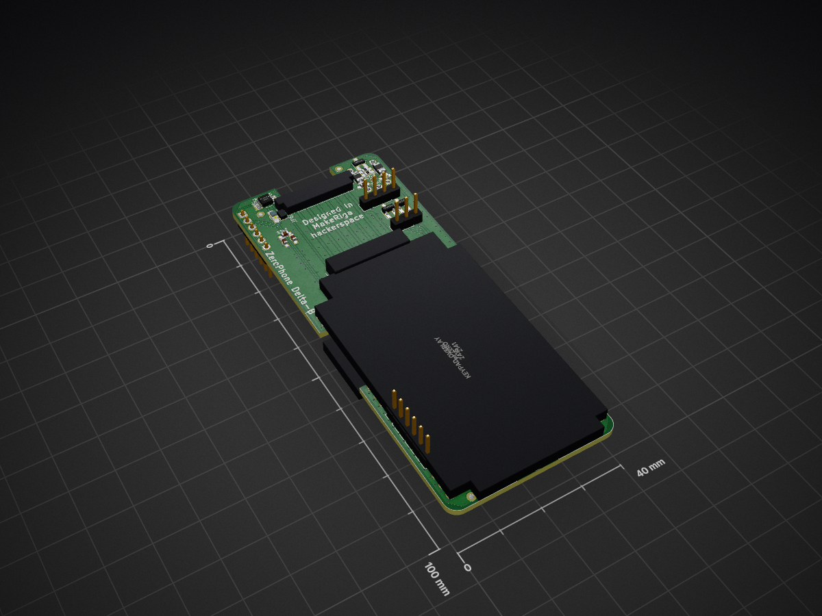
Back pcb
ZeroPhone/ZeroPhone-PCBs
PCB files for ZeroPhone - for gerbers and schematics, go to "Releases" tab!
118 parts148GPL-3.0
 ZeroPhone/ZeroPhone-PCBs148
PCB files for ZeroPhone - for gerbers and schematics, go to "Releases" tab!
Front prototype is an open-source printed circuit board by ZeroPhone, from the ZeroPhone/ZeroPhone-PCBs repository on GitHub, published under the GPL-3.0 licence. It is a 2-layer board of 40 × 100 mm with 97 parts on 85 nets, routed with 1,522 tracks and 402 vias.
It is built around the ATMEGA328P-AU, ESP-12E and BC847B, with the FC68125 and JUMPER3 among its other parts. Its parts include 30 capacitors, 23 resistors, 7 connectors, 5 ICs and 5 diodes. It belongs with the ESP8266 and AVR (ATmega, ATtiny) boards of this library.


KiCad PCB files for ZeroPhone - Delta revision
| Qty | Value | Footprint | References |
|---|---|---|---|
| 9 | 100nF | common-footprints:C_0805_100nF_HandSoldering | C1, C4, C5, C6, C7, C8, C13, C14, C26 |
| 8 | 33pF | Capacitors_SMD:C_0603_HandSoldering | C16, C17, C18, C19, C20, C21, C28, C29 |
| 6 | 47R | common-footprints:R_0805_47R_HandSoldering | R5, R6, R7, R8, R9, R10 |
| 5 | 10K | common-footprints:R_0805_10K_HandSoldering | R3, R4, R11, R12, R13 |
| 5 | 10pF | Capacitors_SMD:C_0603_HandSoldering | C22, C23, C24, C25, C27 |
| 4 | 150R | Resistors_SMD:R_0603_HandSoldering | R1, R2, R20, R21 |
| 4 | JUMPER | Connect:GS2 | JP1, JP2, JP5, JP6 |
| 3 | BAW99 | TO_SOT_Packages_SMD:SOT-23_Handsoldering | D3, D4, D5 |
| 2 | 10uF | Capacitors_SMD:C_1206 | C9, C10 |
| 2 | 18pF | Capacitors_SMD:C_0805_HandSoldering | C2, C3 |
| 2 | 1K8 | Resistors_SMD:R_0603_HandSoldering | R18, R19 |
| 2 | 270R | Resistors_SMD:R_0603_HandSoldering | R14, R15 |
| 2 | 33nF | Capacitors_SMD:C_0603_HandSoldering | C11, C12 |
| 2 | ? | common-footprints:R_0805_10K_HandSoldering | R22, R23 |
| 2 | BC847B | common-footprints:BC847B-SOT-23_Handsoldering | Q1, Q2 |
| 2 | TEST_1P | Measurement_Points:Measurement_Point_Square-SMD-Pad_Small | W1, W2 |
| 1 | 0R | Resistors_SMD:R_0805_HandSoldering | R16 |
| 1 | 100uF | Capacitors_Tantalum_SMD:CP_Tantalum_Case-D_EIA-7343-31_Hand | C15 |
| 1 | 10uF | Capacitors_SMD:C_0805_HandSoldering | C30 |
| 1 | 1K | Resistors_SMD:R_0603_HandSoldering | R17 |
| 1 | 1N4148 | common-footprints:1N4148-D_MiniMELF_Handsoldering | D1 |
| 1 | ATMEGA328P-AU | Housings_QFP:TQFP-32_7x7mm_Pitch0.8mm | IC1 |
| 1 | ATMEGA_CONN | Pin_Headers:Pin_Header_Straight_1x06_Pitch2.54mm | P6 |
| 1 | ATMEGA_MOSI | Measurement_Points:Measurement_Point_Square-SMD-Pad_Small | W7 |
| 1 | AUDIO_CONN | Pin_Headers:Pin_Header_Straight_1x06_Pitch2.54mm | J1 |
| 1 | CONN_01X03 | Pin_Headers:Pin_Header_Straight_1x03_Pitch2.54mm | P4 |
| 1 | CONN_01X04 | Pin_Headers:Pin_Header_Straight_1x04_Pitch2.54mm | P3 |
| 1 | CONN_01X08 | footprints:Top-Display-Header | P2 |
| 1 | CRYSTAL_TH_SMD | footprints:Crystal_HC49_CSTCE | X1 |
| 1 | ESP-12E | ESP12E_SMD:ESP-12E_-1_-22 | U2 |
| 1 | FC68125 | footprints:4P_RPi_AV_jack | JACK1 |
| 1 | FID1 | Fiducials:Fiducial_1mm_Dia_2mm_Outer | TP1 |
| 1 | FID2 | Fiducials:Fiducial_1mm_Dia_2mm_Outer | TP3 |
| 1 | FID3 | Fiducials:Fiducial_1mm_Dia_2mm_Outer | TP5 |
| 1 | FID4 | Fiducials:Fiducial_1mm_Dia_2mm_Outer | TP7 |
| 1 | FID5 | Fiducials:Fiducial_1mm_Dia_2mm_Outer | TP2 |
| 1 | FID6 | Fiducials:Fiducial_1mm_Dia_2mm_Outer | TP4 |
| 1 | FID7 | Fiducials:Fiducial_1mm_Dia_2mm_Outer | TP6 |
| 1 | FID8 | Fiducials:Fiducial_1mm_Dia_2mm_Outer | TP8 |
| 1 | GND | Measurement_Points:Measurement_Point_Square-SMD-Pad_Small | W12 |
| 1 | JUMPER3 | footprints:GS3_SMALL | JP3 |
| 1 | KEYPAD_GPIO | common-footprints:GS2_SMALL | JP4 |
| 1 | KEYPAD_OVERLAY | common-footprints:keypad_overlay | U3 |
| 1 | LED | Capacitors_SMD:C_0805_HandSoldering | D2 |
| 1 | MIC | common-footprints:MICROPHONE | W3 |
| 1 | Pi Zero | footprints:Pi-Zero-Front | U1 |
| 1 | SPI_1.3_OLED | Pin_Headers:Pin_Header_Straight_1x07_Pitch2.54mm | P7 |
| 1 | SPK+ | Measurement_Points:Measurement_Point_Square-SMD-Pad_Small | W5 |
| 1 | SPK- | Measurement_Points:Measurement_Point_Square-SMD-Pad_Small | W4 |
| 1 | SW_Push | common-footprints:SW_SPST_EVQPE1 | SW1 |
| 1 | SwitchableHeader-3x08 | footprints:Pin_Header_Straight_1x08 | P1 |
| 1 | TPA2005 | Housings_SSOP:VSSOP-8_3.0x3.0mm_Pitch0.65mm | U4 |
| 1 | VSYS | Measurement_Points:Measurement_Point_Square-SMD-Pad_Small | W11 |
It measures 40 × 100 mm and has 2 copper layers, 1.6 mm thick.
97 parts, built around the ATMEGA328P-AU, ESP-12E, BC847B and FC68125. The full list of its parts is on this page, with links to each part's symbol and footprint where PCBKit's library has them.
From the ZeroPhone/ZeroPhone-PCBs repository on GitHub, at the commit this page was made from: the board is front_pcb/front_prototype.kicad_pcb. PCBKit opens the board in the browser, with nothing to install.
Its repository publishes it under the GPL-3.0 licence: you may reuse it on that licence's terms (keep the author's notice, and for a copyleft licence share your changes alike).
ZeroPhone/ZeroPhone-PCBs
PCB files for ZeroPhone - for gerbers and schematics, go to "Releases" tab!

ZeroPhone/ZeroPhone-PCBs
PCB files for ZeroPhone - for gerbers and schematics, go to "Releases" tab!

ZeroPhone/ZeroPhone-PCBs
PCB files for ZeroPhone - for gerbers and schematics, go to "Releases" tab!

vgisc/ZeroPhone-PCBs
This is gamma version. It's WIP and is going to be sent to production soon (as soon as last TODOs are finished). You can already order this board, but it's possible the I2C GPIO expander pin mapping is going to change.


tracelabs-pcb/usb-audio-interface
USB-C Audio Interface PCB — UAC2, Headset, Mic Preamp — KiCad 4-Layer


Alihk93/B-W_Master_Slave_RF
Design, validate, and release two manufacturable PCBs that together form a one-way wireless link: a solar-powered remote node (**R_Slave**) transmits a 433.92 MHz ASK/OOK signal to a mains-powered base unit…