2 layers232.1 × 131.2 mm

 ZeniteSolar/MSC19
Voltage or Current Sensor Module for CANBUS with ATmega328p
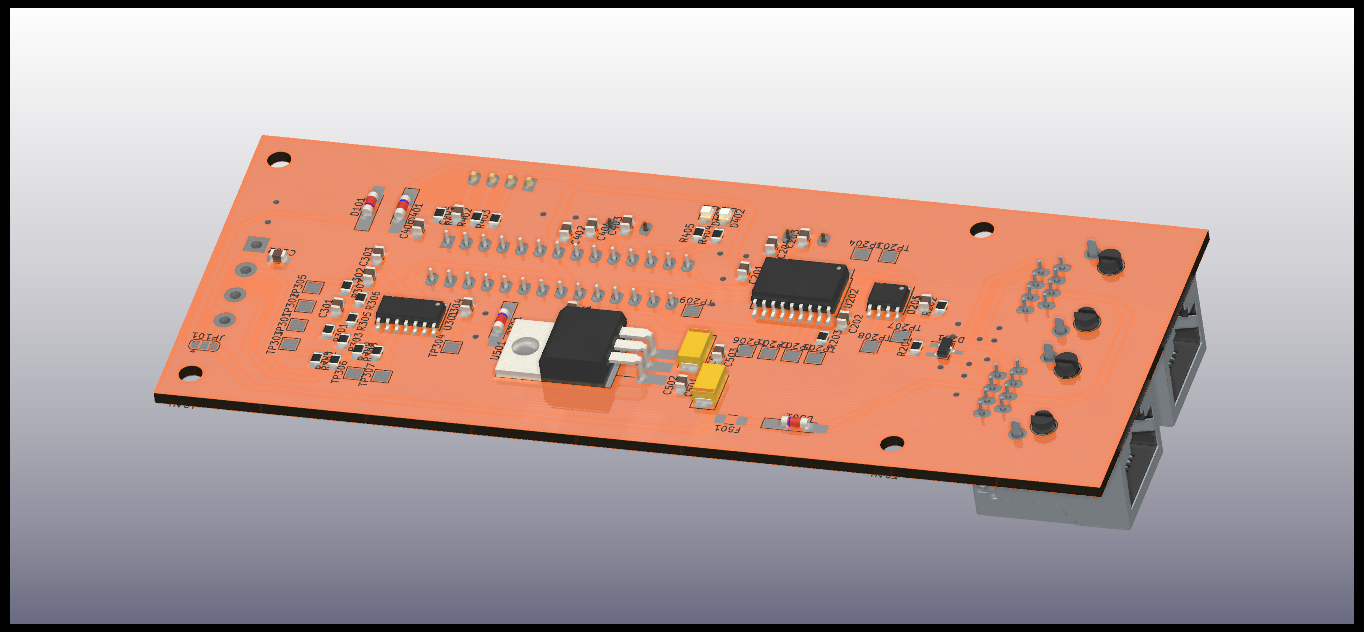
Basicsensormodule is an open-source printed circuit board by ZeniteSolar, from the ZeniteSolar/MSC19 repository on GitHub, published under the GPL-3.0 licence. It is a 2-layer board of 130.2 × 52.1 mm with 77 parts on 59 nets, routed with 391 tracks and 20 vias.
It is built around the ATMEGA328P-PU, MCP2551-I/SN and LM324, with the LM7805, LL4148 and RJ45 among its other parts. Its parts include 20 capacitors, 17 resistors, 7 diodes, 5 ICs and 4 connectors. It belongs with the interfaces and adapters and sensors and measurement boards and the AVR (ATmega, ATtiny) boards of this library.


Módulo Sensor Can 2019
Embarcação Guarapuvu II
Equipe Zênite Solar
Este módulo é reponsável por realizar as medições de tensão ou corrente e enviar pela rede CAN

Medições
Tensões em modo diferencial (banco de baterias).
Corrente de entrada (carga das baterias).
Corrente consumida.
Linearizações
Ensaio de funcionamento com cada sensor.
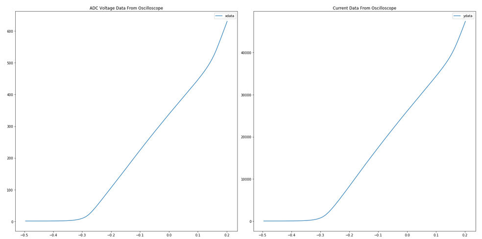
Utilização de métodos matemáticos para determinar a equação que rege o comportamento do sensor, fornecendo uma leitura com melhor precisão.
Envio das informações

Este é um sensor de efeito hall que apresenta em sua saída uma corrente proporcional à corrente que circula por sua janela. É necessário a utilização de um resistor para apresentar um valor de tensão, possibilitando assim a leitura pelo ADC de um microcontrolador. O sinal fornecido pelo sensor passa por uma etapa de filtragem, eliminando possíveis interferências.
Limites elétricos:
Corrente nominal RMS: máx AC 150 [A]
Valor de Pico a Pico: máx 212 [A]
Valores Aplicáveis Para Resistores de Medidas (componente "Rm"):
12V de alimentação e 85°C ambiente. Para ±150A(máx): 0Ω - 40Ω Para ±212A(máx): 0Ω - 3Ω
15V de alimentação e 85°C ambiente. Para ±150A(máx): 0Ω - 78Ω Para ±212A(máx): 0Ω - 30Ω
| Qty | Value | Footprint | References |
|---|---|---|---|
| 10 | 100nF | Capacitor_SMD:C_0805_2012Metric_Pad1.15x1.40mm_HandSolder | C102, C201, C202, C205, C401, C402, C405, C406, C502, C503 |
| 7 | 10k | Resistor_SMD:R_0805_2012Metric_Pad1.15x1.40mm_HandSolder | R203, R301, R303, R304, R308, R309, R401 |
| 7 | 1k | Resistor_SMD:R_0805_2012Metric_Pad1.15x1.40mm_HandSolder | R305, R306, R307, R402, R403, R404, R405 |
| 4 | 100n | Capacitor_SMD:C_0805_2012Metric_Pad1.15x1.40mm_HandSolder | C301, C302, C303, C304 |
| 4 | 22pF | Capacitor_SMD:C_0805_2012Metric_Pad1.15x1.40mm_HandSolder | C203, C204, C403, C404 |
| 4 | MountingHole | MountingHole:MountingHole_3.2mm_M3 | H101, H102, H103, H104 |
| 3 | LL4148 | Diode_SMD:D_MiniMELF_Handsoldering | D101, D401, D501 |
| 2 | 16MHz | Crystal:Crystal_HC49-U_Vertical | Y201, Y401 |
| 2 | 1uF | Capacitor_Tantalum_SMD:CP_EIA-6032-20_AVX-F_Pad2.25x2.35mm_HandSolder | C501, C504 |
| 2 | LED_RED | LED_SMD:LED_0805_2012Metric_Pad1.15x1.40mm_HandSolder | D402, D403 |
| 2 | RJ45 | KicadZeniteSolarLibrary18:RJ45_YH59_01 | J601, J602 |
| 1 | 100k | Resistor_SMD:R_0805_2012Metric_Pad1.15x1.40mm_HandSolder | R302 |
| 1 | 120 | Resistor_SMD:R_0805_2012Metric_Pad1.15x1.40mm_HandSolder | R201 |
| 1 | 4V7 | Diode_SMD:D_MiniMELF_Handsoldering | D301 |
| 1 | 4k7 | Resistor_SMD:R_0805_2012Metric_Pad1.15x1.40mm_HandSolder | R202 |
| 1 | 500mA | Fuse:Fuse_1206_3216Metric_Pad1.42x1.75mm_HandSolder | F501 |
| 1 | ATMEGA328P-PU | Package_DIP:DIP-28_W7.62mm_Socket | U401 |
| 1 | CAN_H | TestPoint:TestPoint_Pad_2.0x2.0mm | TP207 |
| 1 | CAN_L | TestPoint:TestPoint_Pad_2.0x2.0mm | TP208 |
| 1 | INT | TestPoint:TestPoint_Pad_2.0x2.0mm | TP209 |
| 1 | LM324 | Package_SO:SOIC-14_3.9x8.7mm_P1.27mm | U301 |
| 1 | LM7805 | KicadZeniteSolarLibrary18:TO-220-3_Horizontal_TabDown_SMD | U501 |
| 1 | MCP2515-xSO | Package_SO:SOIC-18W_7.5x11.6mm_P1.27mm | U202 |
| 1 | MCP2551-I/SN | Package_SO:SOIC-8_3.9x4.9mm_P1.27mm | U201 |
| 1 | RXCAN | TestPoint:TestPoint_Pad_2.0x2.0mm | TP204 |
| 1 | SC | TestPoint:TestPoint_Pad_2.0x2.0mm | TP205 |
| 1 | SCK | TestPoint:TestPoint_Pad_2.0x2.0mm | TP206 |
| 1 | SENSOR | TerminalBlock:TerminalBlock_bornier-4_P5.08mm | J102 |
| 1 | SI | TestPoint:TestPoint_Pad_2.0x2.0mm | TP201 |
| 1 | SO | TestPoint:TestPoint_Pad_2.0x2.0mm | TP202 |
| 1 | TXCAN | TestPoint:TestPoint_Pad_2.0x2.0mm | TP203 |
| 1 | USART | Connector_PinHeader_2.54mm:PinHeader_1x04_P2.54mm_Vertical | J401 |
| 1 | in+ | TestPoint:TestPoint_Pad_2.0x2.0mm | TP306 |
| 1 | in- | TestPoint:TestPoint_Pad_2.0x2.0mm | TP303 |
| 1 | jmp | Jumper:SolderJumper-3_P1.3mm_Open_RoundedPad1.0x1.5mm | JP101 |
| 1 | op_a_in+ | TestPoint:TestPoint_Pad_2.0x2.0mm | TP307 |
| 1 | op_a_in- | TestPoint:TestPoint_Pad_2.0x2.0mm | TP301 |
| 1 | op_a_out | TestPoint:TestPoint_Pad_2.0x2.0mm | TP302 |
| 1 | op_b_in+ | TestPoint:TestPoint_Pad_2.0x2.0mm | TP305 |
| 1 | op_b_out | TestPoint:TestPoint_Pad_2.0x2.0mm | TP304 |
| 1 | pesd1can | Package_TO_SOT_SMD:SOT-23_Handsoldering | D201 |
It measures 130.2 × 52.1 mm and has 2 copper layers, 1.6 mm thick.
77 parts, built around the ATMEGA328P-PU, MCP2551-I/SN, LM324 and LM7805. The full list of its parts is on this page, with links to each part's symbol and footprint where PCBKit's library has them.
From the ZeniteSolar/MSC19 repository on GitHub, at the commit this page was made from: the board is hardware/basicsensormodule.kicad_pcb. PCBKit opens the board in the browser, with nothing to install.
Its repository publishes it under the GPL-3.0 licence: you may reuse it on that licence's terms (keep the author's notice, and for a copyleft licence share your changes alike).


ZeniteSolar/MSC25
Este projeto consiste em uma placa de circuito impresso (PCB) com firmware embarcado, projetada para realizar a leitura de alta precisão de um sensor de corrente de efeito Hall e transmitir os dados através do…

ZeniteSolar/MCS19
Módulo de Carregamento do Sistema da embarcação solar Guarapuvu II (Zênite Solar)


ZeniteSolar/MIC19
Módulo de Interface do Controle da embarcação solar Guarapuvu II (Zênite Solar)