
2 layers170 × 102.5 mm
ButtonsSuper
ste2425/PSP-Bluetooth
Formerly PSP-Consolizer, PSP-Bluetooth aims to add Bluetooth controller support to the PSP 1K/2K/3K.
26 parts108MIT

 Zekfoo/tactileAGB34
Tactile button mod for the Game Boy Advance
TactileAGB is an open-source printed circuit board by Zekfoo, from the Zekfoo/tactileAGB repository on GitHub. It is a 2-layer board of 30.8 × 42.5 mm with 21 parts on 13 nets, routed with 388 tracks and 0 vias.
It is built around the SKRRABE010. It belongs with the retro computing and games boards of this library.
CURRENT VERSION - REV 1.1
This mod for the Game Boy Advance (AGB) was inspired by makho's AGB_TACT project which added tactile buttons to the AGB to create a similar clicky feel to the GBA SP and more recent Nintendo handhelds.
Developed from the ground up, this implementation offers a no-wires-required solution, consisting of 3 flex breakout boards for the DPAD, A/B, and START/SELECT.
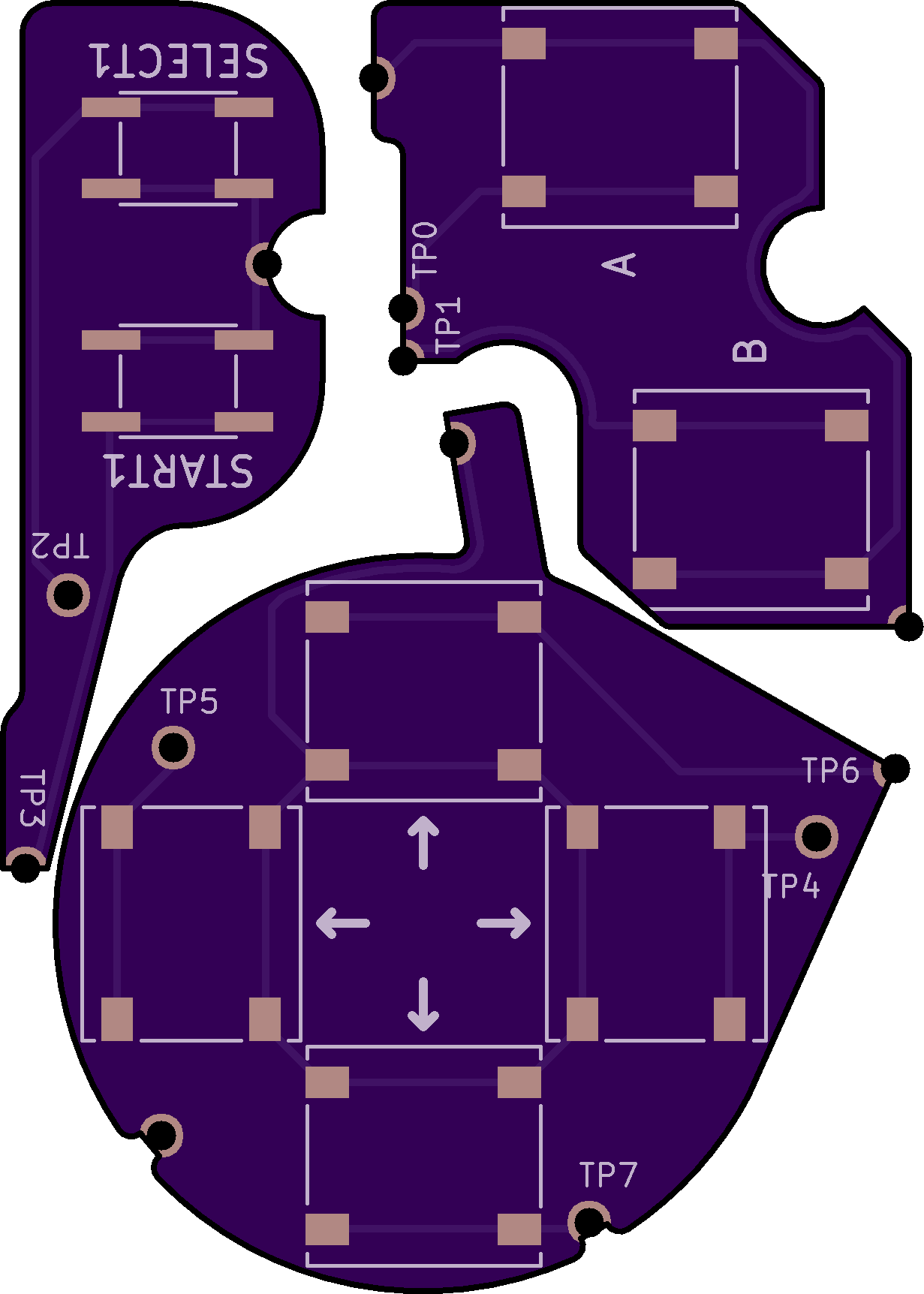
This mod is only compatible with AGB-001.
Due to variability between OEM and different aftermarket buttons and membranes, some adjustments may need to be made to adjust the button height and travel distances - more details in the Installation section.
Compatibility with the IPS v2 mod's brightness controls is ensured - just solder the SELECT wire overtop of the TP2 hole.
Flex board order link ($20.70 for 3 sets) - OSH Park
SKRRABE010 (for DPAD and A/B - GBA SP Buttons) - Mouser
SOG-152ANT (for START/SELECT) - Digikey
As with all hardware mods, you risk irreparable damage to your device if the proper precautions are not taken. Feel free to reach out for any questions or troubleshooting.
General:
DPAD
A/B
START/SELECT
Button height/travel
Thanks to makho for his original project idea and video.
Thanks to HDR for compiling his Nintenfo repository, which made development much swifter.

This work is licensed under a Creative Commons Attribution-NonCommercial-ShareAlike 4.0 International License.
Feel free to modify this design however you like, but please make sure to give credit where it is due. I encourage you to share your improvements with the rest of the Gameboy modding community at the Gameboy Discord and Subreddit
Under this license, you are not permitted to profit from or commercialize this design in any part without my express permission.
| Qty | Value | Footprint | References |
|---|---|---|---|
| 13 | TestPoint | AGBTactile:Hole-1.5mm | FR2, GND2PAD1, GND3PAD1, L-SHIELDING1, TP0, TP1, TP2, TP3, TP4, TP5, TP6, TP7, VDD-15 |
| 6 | SKRRABE010 | tactileAGB:SKRRABE010 | ↑, ↑, ↑, ↑, A, B |
| 2 | SOG-152ANT | tactileAGB:SOG-15xANT | SELECT1, START1 |
It measures 30.8 × 42.5 mm and has 2 copper layers, 1.6 mm thick.
21 parts, built around the SKRRABE010. The full list of its parts is on this page, with links to each part's symbol and footprint where PCBKit's library has them.
From the Zekfoo/tactileAGB repository on GitHub, at the commit this page was made from: the board is tactileAGB.kicad_pcb. PCBKit opens the board in the browser, with nothing to install.
Its repository states no licence, so its author keeps all rights: ask Zekfoo before reusing the design.
ste2425/PSP-Bluetooth
Formerly PSP-Consolizer, PSP-Bluetooth aims to add Bluetooth controller support to the PSP 1K/2K/3K.

gusmanb/logicanalyzer
24 channel, 100Msps logic analyzer hardware and software

mntmn/amiga2000-gfxcard
MNT VA2000, an Open Source Amiga 2/3/4000 Graphics Card (Zorro II/III), written in Verilog


hackclub/OnBoard
💡 Join 1,000 teenagers and make your first PCB with a $100 grant!

drandyhaas/KiCadRoutingTools
A set of Python/Rust tools to aid routing in KiCad

Arrow-air/project-quiver
Project Quiver documentation, designs, and project artifacts.
