
2 layers45.3 × 75.9 mm

 ZBZFirst/KiCad-Projects1
Custom ESP32 BLE HID controller + matching PCB design.
Receiver is an open-source printed circuit board by ZBZFirst, from the ZBZFirst/KiCad-Projects repository on GitHub. It is a 2-layer board with 3 parts on 38 nets, routed with 22 tracks and 0 vias.
It is built around the ADS1115IDGS. Its parts include 1 IC and 1 connector.
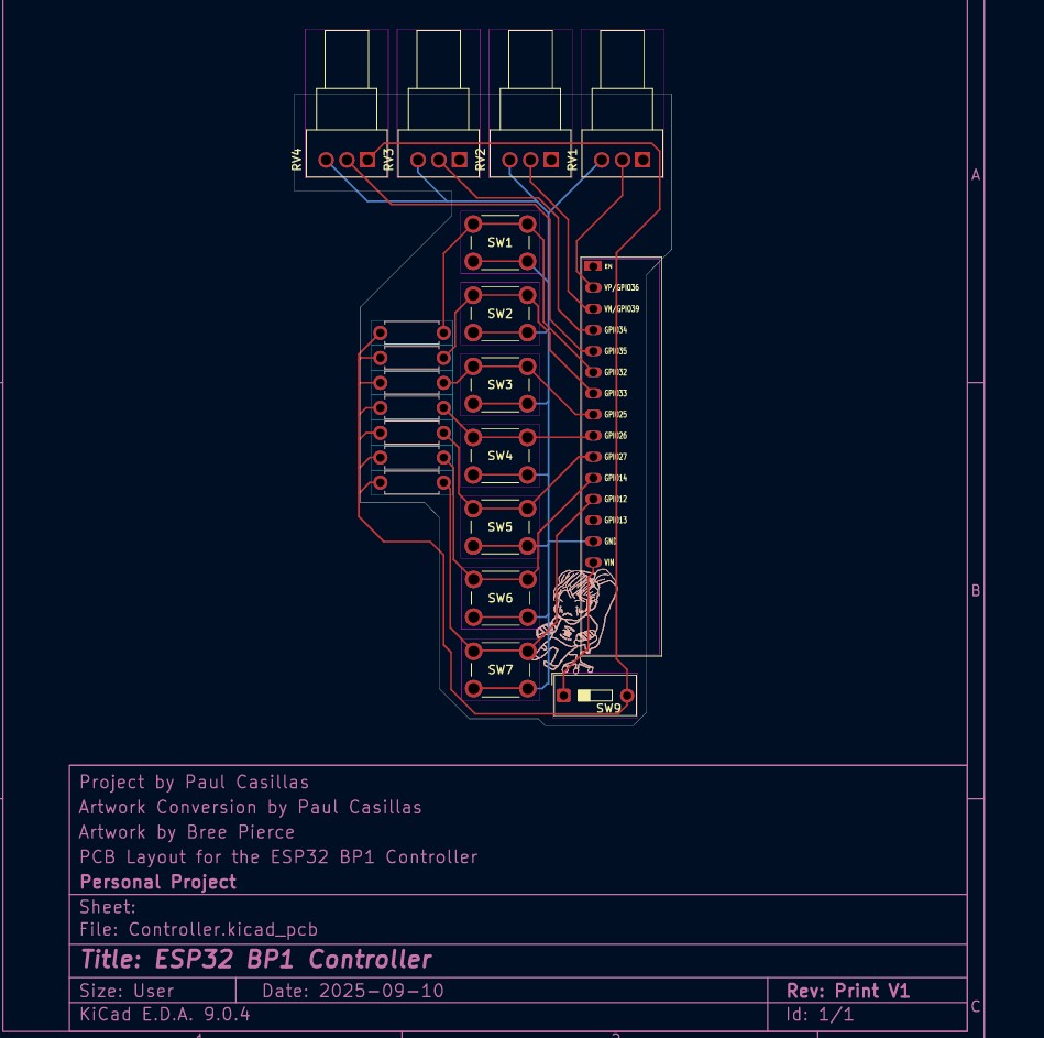
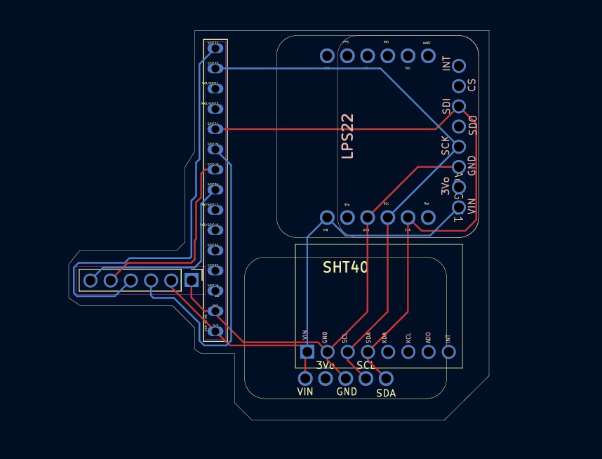
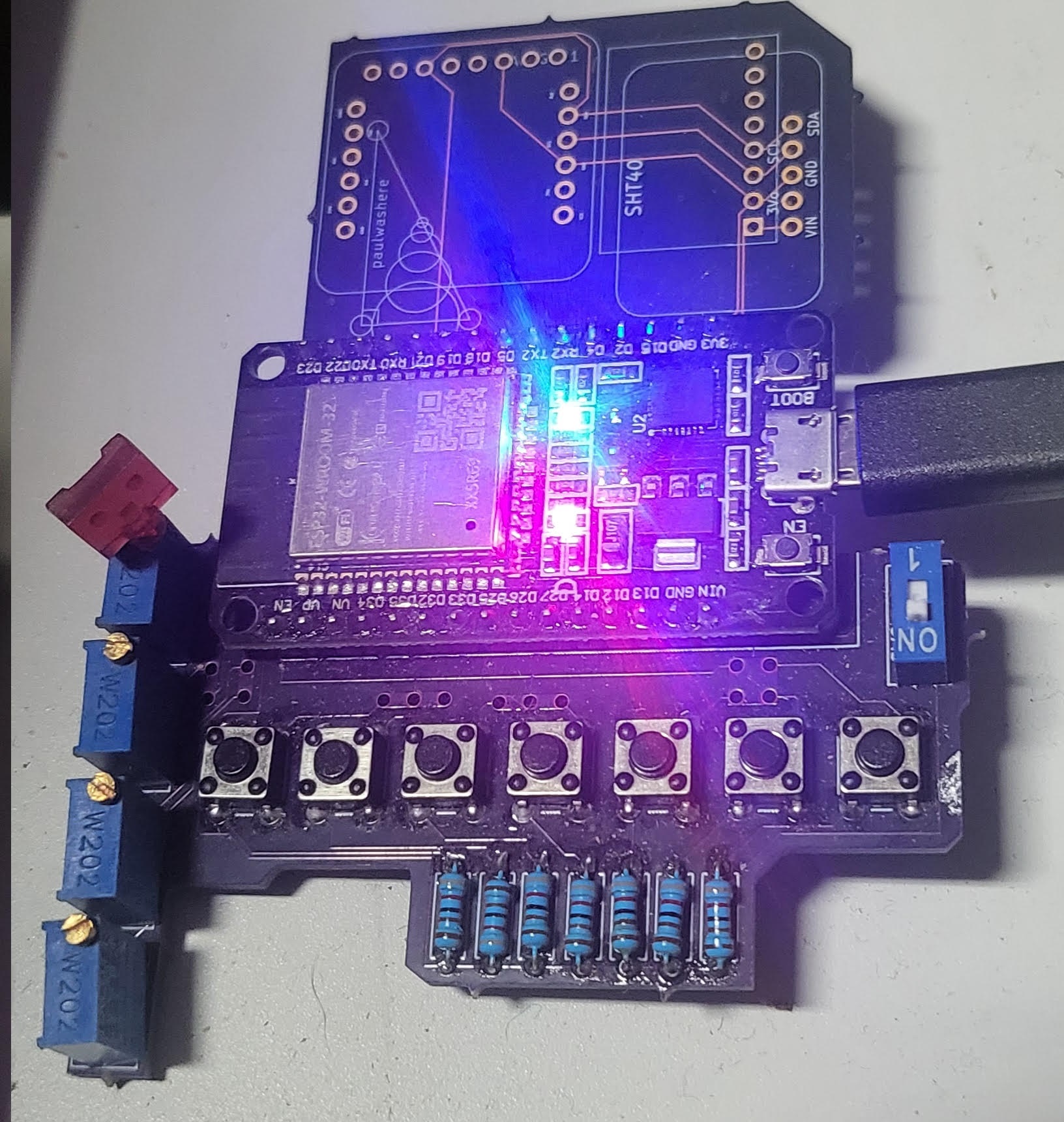
Custom ESP32 BLE HID controller + matching PCB design.
This project combines:
Designed as a personal hardware controller that behaves like a wireless keyboard/mouse macro pad.
ESP32-based custom PCB with:
KiCad layout included in repository.
File:
hardware/Controller.kicad_pcbThis board is designed specifically to run the included firmware.
The controller has 3 operating groups.
Button 6 cycles groups.
Button 7 forces disconnect (reboot).
| Button | Action |
|---|---|
| B1 | Ctrl + C |
| B2 | Ctrl + V |
| B3 | Ctrl + X |
| B4 | Ctrl + Z |
| B5 | 8-second mouse movement run |
LED: solid ON when connected
| Button | Action |
|---|---|
| B1 | Windows search → cmd → ssh CB37 |
| B2 | Launch Edge |
| B3 | Launch Super |
| B4 | Launch Arduino |
| B5 | Launch Bluetooth |
LED: 2 blink pattern
Toggle behaviors:
| Button | Mode |
|---|---|
| B1 | Auto left click |
| B2 | Auto right click |
| B3 | Auto middle click |
| B4 | Spam key “E” |
| B5 | Spam key “F” |
Press the same button again to stop.
LED: 3 blink pattern
Blink sequence repeats every 2 seconds.
Open:
firmware/PaulsESP32.inoCompile and upload to the board.
Designed primarily for Windows but functions as a generic BLE HID device.
firmware/
  PaulsESP32.ino

hardware/
  Controller.kicad_pcb
schematics/PCB + firmware design: Paul Casillas
Artwork: Bree Pierce
Personal project.
MIT — free to modify and build.
file is in
AutoClicker/AutoClickerbyController.ino
| Qty | Value | Footprint | References |
|---|---|---|---|
| 1 | ADS1115IDGS | UserDefined:ADS1115FootPrint | U1 |
| 1 | AveaLogic | Connector_Dsub:DSUB-25_Pins_Horizontal_P2.77x2.84mm_EdgePinOffset9.90mm_Housed_MountingHolesOffset11.32mm | J1 |
| 1 | ~ | UserDefined:ESP32-DEVKITV1-Paul-Half2 | ESP32 Right Side1 |


joeltroughton/uSMU
Credit card-sized, USB-powered 4 quadrant source-measure unit hardware and firmware

dridri/bcflight
Raspberry Pi based drone flight controller and remote control

Bylin-code/Stradex1
STRADEX1 Documentation and Build Instructions ============== I've always wanted to put my violin skills to use in a MIDI environment, but there really isn't a controller on the market that can emulate the feel of a…


luftaquila/monolith
DIY wireless real-time datalogging platform for Student Formula and Baja.

doppelgrau/esp32-f9p-io-board
An IO-PCB (two motor-driver/H-bridge, CAN, RS232, ADS1115, relay, ethernet, ardusimple f9p compatible connector) with an ESP32 for 12V power, three 15V tolerant analog inputs, three 5V tolerant inputs.


joeltroughton/nanoAmmeter
A small ammeter for measuring printed glucose biosensors
3 parts, built around the ADS1115IDGS. The full list of its parts is on this page, with links to each part's symbol and footprint where PCBKit's library has them.
From the ZBZFirst/KiCad-Projects repository on GitHub, at the commit this page was made from: the board is Receiver/Receiver.kicad_pcb and its schematic Attachment2/Attachment2.kicad_sch. PCBKit opens the board in the browser, with nothing to install.
Its repository states no licence, so its author keeps all rights: ask ZBZFirst before reusing the design.