6 layers49.3 × 39.3 mm
VoronToolheadPCB
shxshxshxshx/VoronToolheadPCB
USB Toolhead Board for Voron Stealthburner
99 parts2GPL-3.0

 z2amiller/ocn-ePaper
CR123A elapsed-time counter with a 2.13-inch e-paper display and a magnetic off switch (MSP430FR2111, KiCad 10, CERN-OHL-P v2)
Ocn ePaper is an open-source printed circuit board by z2amiller, from the z2amiller/ocn-ePaper repository on GitHub, published under the CERN-OHL-P-2.0 licence. It is a 2-layer board of 27 × 65.3 mm with 36 parts on 34 nets, routed with 179 tracks and 114 vias.
It is built around the MSP430FR2422IPW16, 5819WS and SI1308EDL. Its parts include 18 capacitors, 4 resistors, 4 diodes, 1 IC and 1 transistor. It belongs with the lEDs and displays boards and the MSP430 boards of this library.


A battery-powered elapsed-time counter with a 2.13-inch e-paper display and a magnetic off switch. While a magnet sits at the marked end, the board is switched off. Take the magnet away and it powers up and counts elapsed time in hours and minutes, up to 99:59 (about 100 hours). Put the magnet back and it powers down several seconds later, leaving the last count on the display; the next time the magnet comes off, counting starts again from 00:00.
It is the e-paper version of ocn-LCD, which uses a segment LCD.
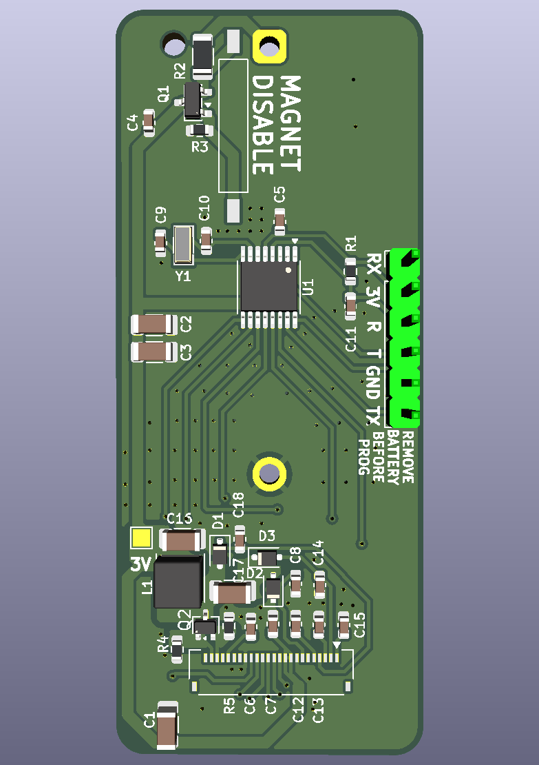
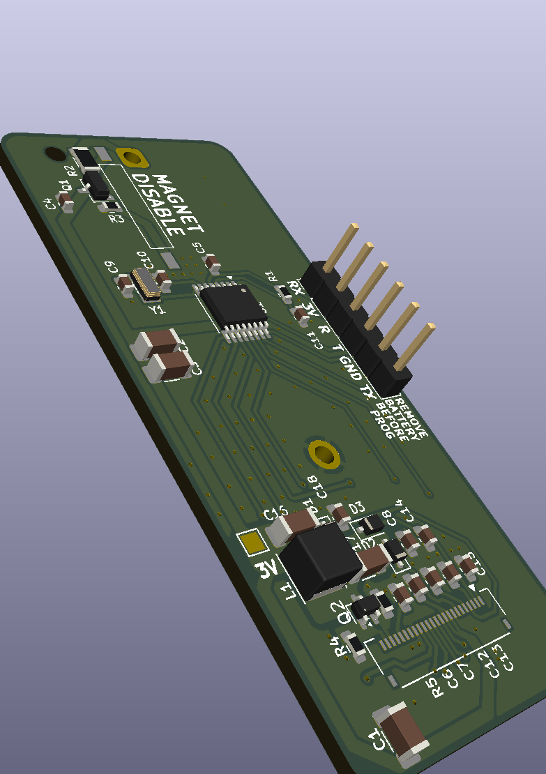
The renders leave out the e-paper panel (it lies over the front), its socket, the reed switch and the CR123A holder (on the back), which have no 3D models. They show a header in J1, which stays empty on a finished board.
Status: revision 0.1, not yet built. Firmware will be added to this repository. The folded tail's pin order has not yet been checked against a real panel.
Estimates at 3.0 V and 25 °C, from the TI datasheet (SLASE78) and Good Display's spec for the panel. They will be replaced by measurements once the firmware is in.
| Item | Counting (magnet away) | Off (magnet in place) | Basis |
|---|---|---|---|
| MCU asleep (LPM3.5), with the 32 kHz crystal and RTC running | 0.44 µA | 0 | Datasheet 0.66 µA typical with the supervisor (SVS) on; turning it off saves about 0.22 µA |
| Panel controller in deep sleep between updates | 1 µA (5 µA max) | 0 | Good Display spec |
| Display updates, once a minute | ~50 µA | 0 | 3.5 mA while updating, 0.42 s for a partial update and 3 s for a full one, with a full refresh after every five partial ones as Good Display recommends |
| MCU awake for each update (writing the image, waiting on BUSY) | ~0.2 µA | 0 | ~10 ms at ~1 mA per update, then light sleep while the panel updates |
| Gate pull-down R3 (10 MΩ across the cell while the reed is closed) | 0 | 0.3 µA | 3.0 V / 10 MΩ |
| Q1 MOSFET leakage while off | – | a few nA | Typical; the datasheet maximum is specified at 30 V |
| Hold-up capacitors, leakage | ~1 nA | 0 | MLCC insulation resistance |
| Reset pull-up, reed switch, unused pins (driven low) | 0 | 0 | No DC path |
| Total | about 52 µA | about 0.3 µA |
The display updates dominate. One partial update uses as much charge as about 17 minutes of sleep, and a full refresh as about 2 hours, so the update rate sets the battery life.
Estimated runtime on one CR123A (1,500 mAh nominal), allowing about 1 %/year for the cell's own self-discharge:
| Mode | Average draw | Estimated runtime |
|---|---|---|
| Counting, display updated once a minute | about 52 µA | about 3 years |
| Counting, display updated every 10 minutes | about 6–10 µA | over 10 years |
| Off (magnet in place) | about 0.3 µA | decades |
The last two are longer than a CR123A's rated shelf life of about 10 years, so in practice the cell's age sets the limit, not this circuit. Cold reduces the cell's usable capacity, and the panel is specified to update only between 0 and 50 °C.
Firmware choices that keep it there:
The reed switch is at the end marked MAGNET DISABLE and runs along the length of the board. It responds to field along its own length, so use a magnet magnetized through its flat faces (a neodymium cylinder or disc), at that end, with its axis along the board and its face toward the board's end. SW1's axis is 3.2 mm from the board's centreline, so a magnet centred on the board's end lines up with it closely. A model of a typical 10 × 8 mm N42 cylinder (no nearby steel) gives several times the switch's ~2–3 mT pull-in out to about 20 mm, even 9 mm off the switch's axis.
Steel nearby. The CR123A's case is steel, and it sits on the back directly behind the switch. That changes the field around the switch, and its effect hasn't been measured yet. Check the switching distance on the bench with a cell fitted.
The switch lets go only once the magnet is a few centimeters away (the same model puts it at about 35–40 mm in line), so move the magnet well clear to start counting.
| Ref | Part | LCSC |
|---|---|---|
| U1 | TI MSP430FR2111IPW, TSSOP-16 | C2052845 |
| DS2 | Good Display GDEY0213B74 2.13" e-paper panel, in a Hirose FH34SRJ-24S-0.5SH socket | C324726 (the socket) |
| BT1 | MYOUNG BH-123A-A1CJ002 CR123A holder, through-hole | C5290177 |
| SW1 | Littelfuse 59170-1-S-00-D reed switch, normally open, 10–15 AT | C315909 |
| Q1 | AO3401A P-channel MOSFET, SOT-23 (power switch) | C15127 |
| Q2 | Vishay Si1308EDL N-channel MOSFET, SOT-323 (display booster) | C469327 |
| L1 | Changjiang FNR4030S470MT 47 µH inductor, 4 × 4 mm | C167888 |
| D1–D3 | 1N5819WS Schottky diode, SOD-323 | C191023 |
| Y1 | 32.768 kHz crystal, 3215, 12.5 pF | C32346 |
Every part in the BOM carries its LCSC number. The panel itself comes from Good Display; DS2's BOM line is its socket. J1 and TP3 are left out of the BOM and the placement file, and so are BT1 and SW1, which are fitted by hand. The passives are 0603 and 1206.
The MCU is programmed over Spy-Bi-Wire from the eZ-FET programmer on a TI MSP-EXP430FR4133 LaunchPad. Any MSP430 LaunchPad with an eZ-FET should also work. J1, on the board's long edge, carries the four programming signals plus the MCU's serial port. It is a row of six 0.1-inch holes that stays empty: the panel covers it once fitted.
Take the cell out. The LaunchPad powers the board at 3.3 V. With the magnet away, Q1 is on and would pass that straight back into the cell, and a CR123A must never be charged. The silkscreen beside J1 says so too.
Pull every jumper off the LaunchPad's J101 isolation block. That disconnects the LaunchPad's own MCU, so the eZ-FET talks only to this board.
Connect J1. Push a straight 6-pin header into J1's holes without soldering it, holding it tilted slightly so the pins press against the hole walls. Wire it to J101 with dupont jumpers, using the J101 pins on the eZ-FET (emulator) side, not the side that runs to the LaunchPad's own MCU:
| ocn-ePaper J1 | LaunchPad J101, eZ-FET side |
|---|---|
| 3V | 3V3 |
| R | SBW RST |
| T | SBW TST |
| GND | GND |
| RX (optional, serial) | RXD |
| TX (optional, serial) | TXD |
The serial names match straight across. J101 labels its pins from the target MCU's point of view, so its RXD carries data into this board's RX.
Flash the firmware with TI UniFlash or Code Composer Studio. Select the MSP430FR2111 and the LaunchPad's eZ-FET as the connection. A command-line recipe will come with the firmware.
Unplug the LaunchPad before measuring current or fitting the cell. The programming and serial lines draw current of their own.
Serial port. RX and TX are on P1.2 and P1.3. They share the MCU's only serial block with the panel's SPI, so firmware switches the block between the two.
Measuring battery current. R2 (1 Ω, 1206) sits in series with the cell. Lift it and connect a current meter across its pads. TP3 is a test pad on the switched 3 V supply.
ocn-ePaper.kicad_pro, .kicad_sch and .kicad_pcb: the KiCad 10 project. The board is
27 × 65.3 mm, two layers.lib/: the board's own symbols and footprints: the MSP430FR2111, the GDEY0213B74 and its
folded-tail footprint (the socket, plus the panel's outline on the User.Drawings layer), the CR123A
holder and the reed switch. The project's library tables point at this folder, so the project opens
without any other library installed.Licensed under the CERN Open Hardware Licence Version 2 – Permissive (CERN-OHL-P v2). See LICENSE and NOTICE.
You may make, modify, and sell boards from these files, with no obligation to publish your changes.
| Qty | Value | Footprint | References |
|---|---|---|---|
| 10 | 1u | Capacitor_SMD:C_0603_1608Metric | C4, C5, C6, C7, C8, C12, C13, C14, C15, C18 |
| 5 | 4.7u | Capacitor_SMD:C_1206_3216Metric | C1, C2, C3, C16, C17 |
| 4 | 5819WS | Diode_SMD:D_SOD-323F | D1, D2, D3, D4 |
| 2 | 20p | Capacitor_SMD:C_0603_1608Metric | C9, C10 |
| 1 | 10M | Resistor_SMD:R_0603_1608Metric | R3 |
| 1 | 1M | Resistor_SMD:R_0603_1608Metric | R4 |
| 1 | 1n | Capacitor_SMD:C_0603_1608Metric | C11 |
| 1 | 2R2 | Resistor_SMD:R_0603_1608Metric | R5 |
| 1 | 32.768k | Crystal:Crystal_SMD_3215-2Pin_3.2x1.5mm | Y1 |
| 1 | 3V | TestPoint:TestPoint_Pad_1.5x1.5mm | TP3 |
| 1 | 47K | Resistor_SMD:R_0603_1608Metric | R1 |
| 1 | 47u | Inductor_SMD:L_Changjiang_FNR4030S | L1 |
| 1 | CR123 | LowPower:BatteryHolder_MYOUNG_BH-123A-A1CJ002_1xCR123A | BT1 |
| 1 | Current Measure | Jumper:SolderJumper-2_P1.3mm_Bridged_Pad1.0x1.5mm | JP1 |
| 1 | GDEY0213B74 | LowPower:EPD_GDEY0213B74_FoldedUnder_Hirose_FH34SRJ-24S-0.5SH | DS2 |
| 1 | MSP430FR2422IPW | Package_SO:TSSOP-16_4.4x5mm_P0.65mm | U2 |
| 1 | PROG | Connector_PinHeader_2.54mm:PinHeader_1x04_P2.54mm_Vertical | J1 |
| 1 | REED (NO) | LowPower:SW_SPST_REED_Littelfuse_59170_GullWing | SW1 |
| 1 | SI1308EDL | Package_TO_SOT_SMD:SOT-323_SC-70 | Q2 |
shxshxshxshx/VoronToolheadPCB
USB Toolhead Board for Voron Stealthburner

Michael-Manning/E-Paper-Climate-Logger
Firmware, PCB, and enclosure for the Weathergotchi E-Paper climate logger.


gab-k/RP2040-Decoder
Cost effective DIY DCC Decoder for model railroad locomotives

EnriqueNeyra/Aeroq
An Indoor Air Quality Monitor Powered by ESP32, SCD40, and SEN54

EnriqueNeyra/aether
All-in-one home air quality monitor measuring Temp, Humidity, CO2, VOCs, Particulate Matter, and NOx. Powered by ESP32-C3 running esphome, and built with Home Assistant integration


solderable/storm-tracker-hardware
Open-source-ready Storm Tracker hardware design, documentation, BOM, and manufacturing package
It measures 27 × 65.3 mm and has 2 copper layers, 1.6 mm thick.
36 parts, built around the MSP430FR2422IPW16, 5819WS and SI1308EDL. The full list of its parts is on this page, with links to each part's symbol and footprint where PCBKit's library has them.
From the z2amiller/ocn-ePaper repository on GitHub, at the commit this page was made from: the board is ocn-ePaper.kicad_pcb and its schematic ocn-ePaper.kicad_sch. PCBKit opens the board in the browser, with nothing to install.
Its repository publishes it under the CERN-OHL-P-2.0 licence: you may reuse it on that licence's terms (keep the author's notice, and for a copyleft licence share your changes alike).