2 layers60 × 30 mm
Controller
google/mozc-devices
Circuit diagrams and firmware source code for Gboard DIY keyboards
11 parts3kApache-2.0

 yychia131/irsensorpcb
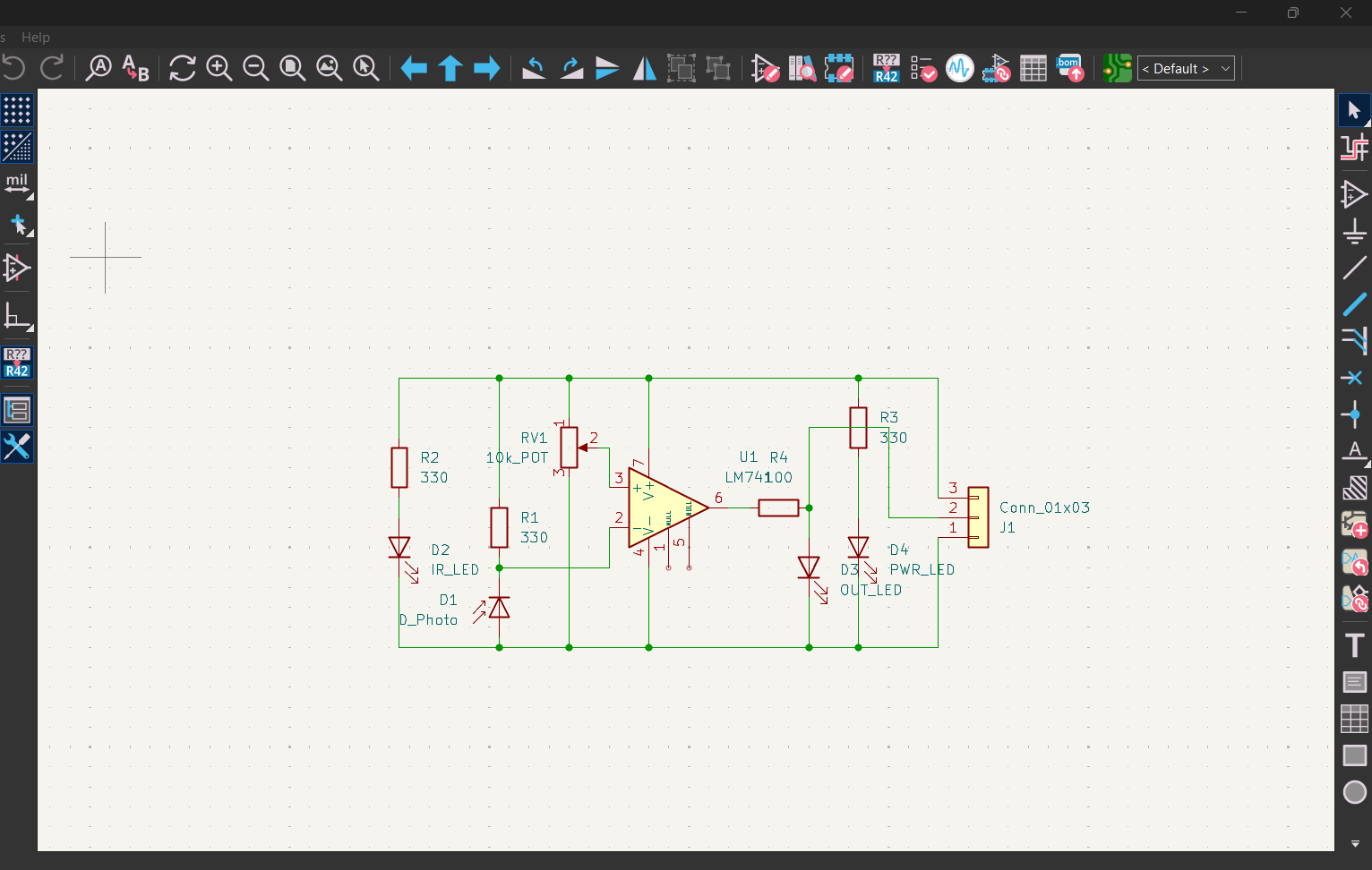
A custom PCB designed in KiCad 8 that detects nearby objects using an IR LED and photodiode pair, processed through an LM741 op-amp comparator circuit with adjustable sensitivity via a potentiometer.
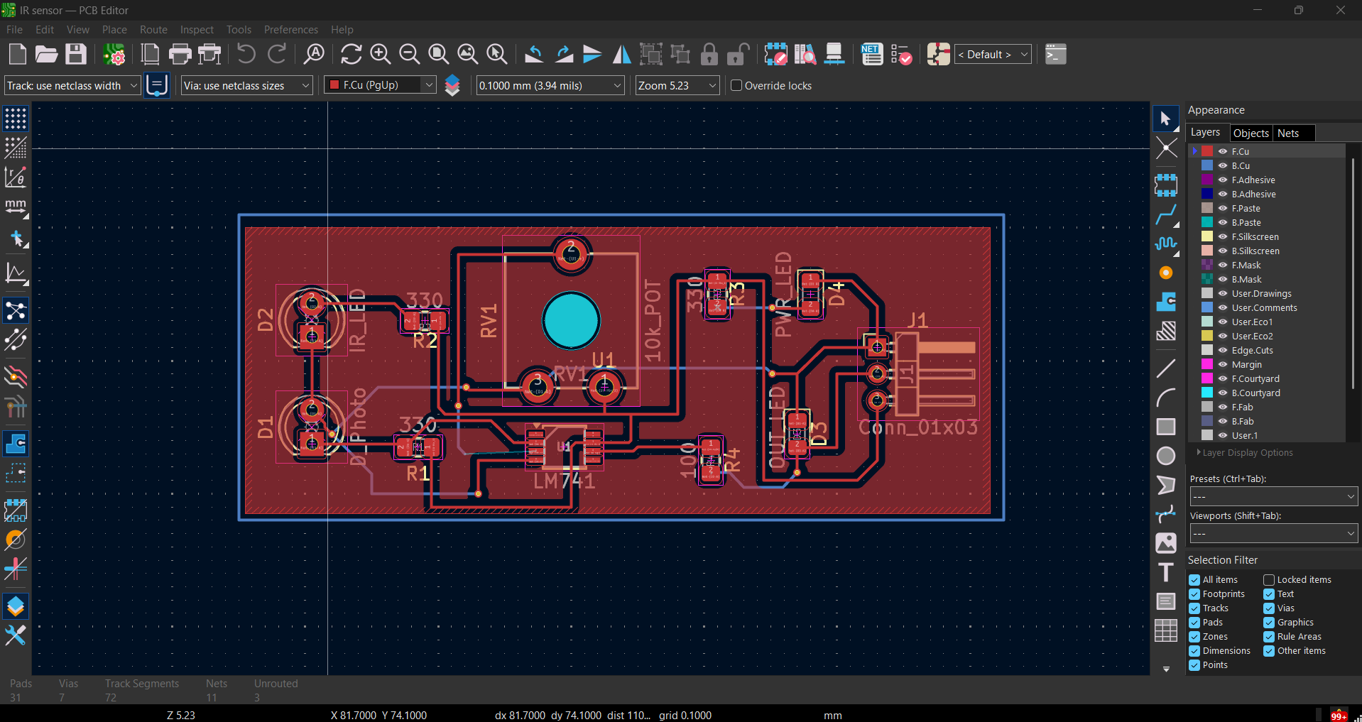
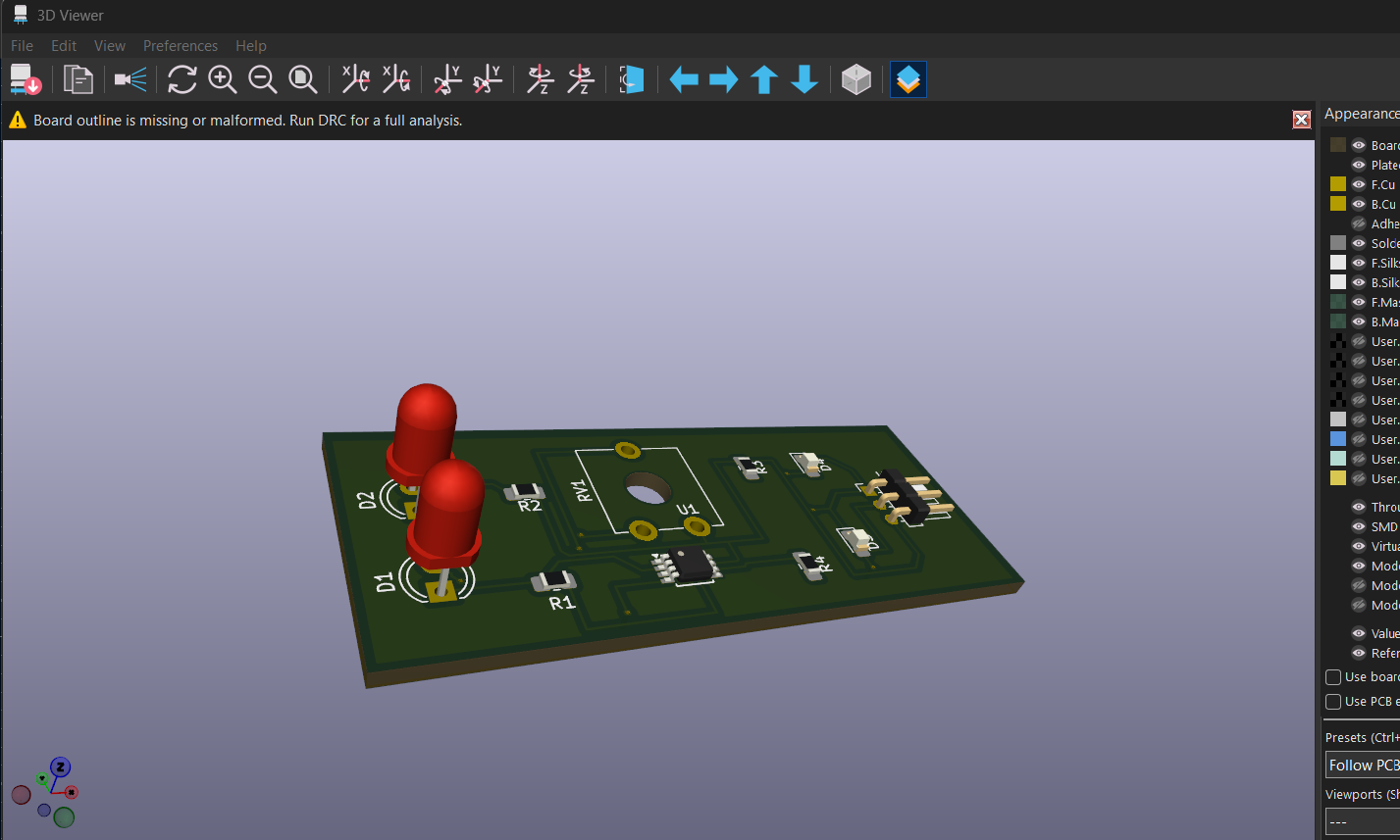
IR sensor is an open-source printed circuit board by yychia131, from the yychia131/irsensorpcb repository on GitHub. It is a 2-layer board with 11 parts on 11 nets, routed with 72 tracks and 7 vias.
Its parts include 4 resistors, 4 diodes, 1 IC and 1 connector. It belongs with the sensors and measurement boards of this library.
A custom PCB designed in KiCad 8 that detects nearby objects using an IR LED and photodiode pair, processed through an LM741 op-amp comparator circuit with adjustable sensitivity via a potentiometer.
| Reference | Component | Description |
|---|---|---|
| U1 | LM741 | Op-amp configured as comparator |
| D1 | D_Photo | Photodiode — IR receiver |
| D2 | IR_LED | Infrared emitter LED |
| D3 | OUT_LED | Output indicator LED |
| D4 | PWR_LED | Power indicator LED |
| RV1 | 10k_POT | Potentiometer — sensitivity adjustment |
| R1–R4 | 330Ω | Current limiting resistors |
| J1 | Conn_01x03 | 3-pin output connector |
| Qty | Value | Footprint | References |
|---|---|---|---|
| 3 | 330 | Resistor_SMD:R_0805_2012Metric_Pad1.20x1.40mm_HandSolder | R1, R2, R3 |
| 1 | 100 | Resistor_SMD:R_0805_2012Metric_Pad1.20x1.40mm_HandSolder | R4 |
| 1 | 10k_POT | Potentiometer_THT:Potentiometer_ACP_CA9-V10_Vertical_Hole | RV1 |
| 1 | Conn_01x03 | Connector_PinHeader_2.00mm:PinHeader_1x03_P2.00mm_Horizontal | J1 |
| 1 | D_Photo | LED_THT:LED_D4.0mm | D1 |
| 1 | IR_LED | LED_THT:LED_D4.0mm | D2 |
| 1 | LM741 | Package_SO:TSSOP-8_3x3mm_P0.65mm | U1 |
| 1 | OUT_LED | LED_SMD:LED_0805_2012Metric_Pad1.15x1.40mm_HandSolder | D3 |
| 1 | PWR_LED | LED_SMD:LED_0805_2012Metric_Pad1.15x1.40mm_HandSolder | D4 |
11 parts. The full list of its parts is on this page, with links to each part's symbol and footprint where PCBKit's library has them.
From the yychia131/irsensorpcb repository on GitHub, at the commit this page was made from: the board is IR sensor.kicad_pcb and its schematic IR sensor.kicad_sch. PCBKit opens the board in the browser, with nothing to install.
Its repository states no licence, so its author keeps all rights: ask yychia131 before reusing the design.
google/mozc-devices
Circuit diagrams and firmware source code for Gboard DIY keyboards


FrameworkComputer/ExpansionCards
Reference designs and documentation to create Expansion Cards for the Framework Laptop

hoglet67/RGBtoHDMI
Bare-metal Raspberry Pi project that provides pixel-perfect sampling of Retro Computer RGB/YUV video and conversion to HDMI

hackclub/OnBoard
💡 Join 1,000 teenagers and make your first PCB with a $100 grant!


tardate/LittleArduinoProjects
a collection of "Little Electronic & Arduino Projects", most involving electronics or an Arduino in one way or another!

basilfx/TRADFRI-Hacking
Hacking IKEA TRÅDFRI products, such as light bulbs, window blinds and other accessories.