4 layers75 × 40 mm

 yuta2k/RL7023-USB
Wi-SUN モジュール「MB-RL7023-11/DSS」を USB Type-C デバイスとして扱うための基板
RL7023-USB is an open-source printed circuit board by yuta2k, from the yuta2k/RL7023-USB repository on GitHub, published under the MIT licence. It is a 4-layer board of 50 × 25 mm with 33 parts on 45 nets, routed with 210 tracks and 95 vias.
It is built around the FT231XS-R, MIC5365-3.3YD5-TR and USBLC6-2P6, with the DF12NB(3.0)-20DS-0.5V(51), LTST-C190EKT and LTST-C190GKT among its other parts. Its parts include 9 resistors, 8 capacitors, 3 ICs, 3 diodes and 2 connectors.


Wi-SUN モジュール「MB-RL7023-11/DSS」を USB Type-C デバイスとして扱うための基板です。
USB-UART コンバータ「FT231X」を採用しており、USB 経由でシリアル通信が可能です。
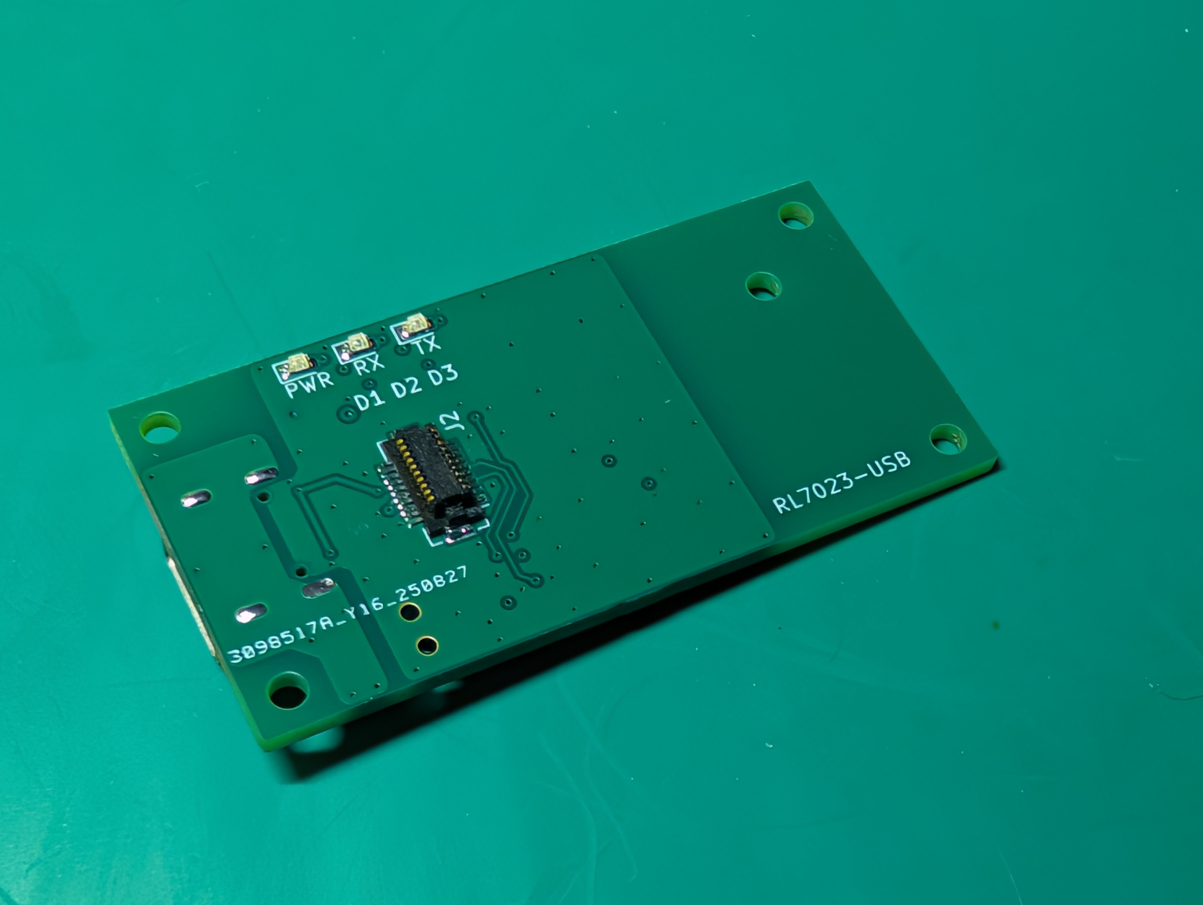
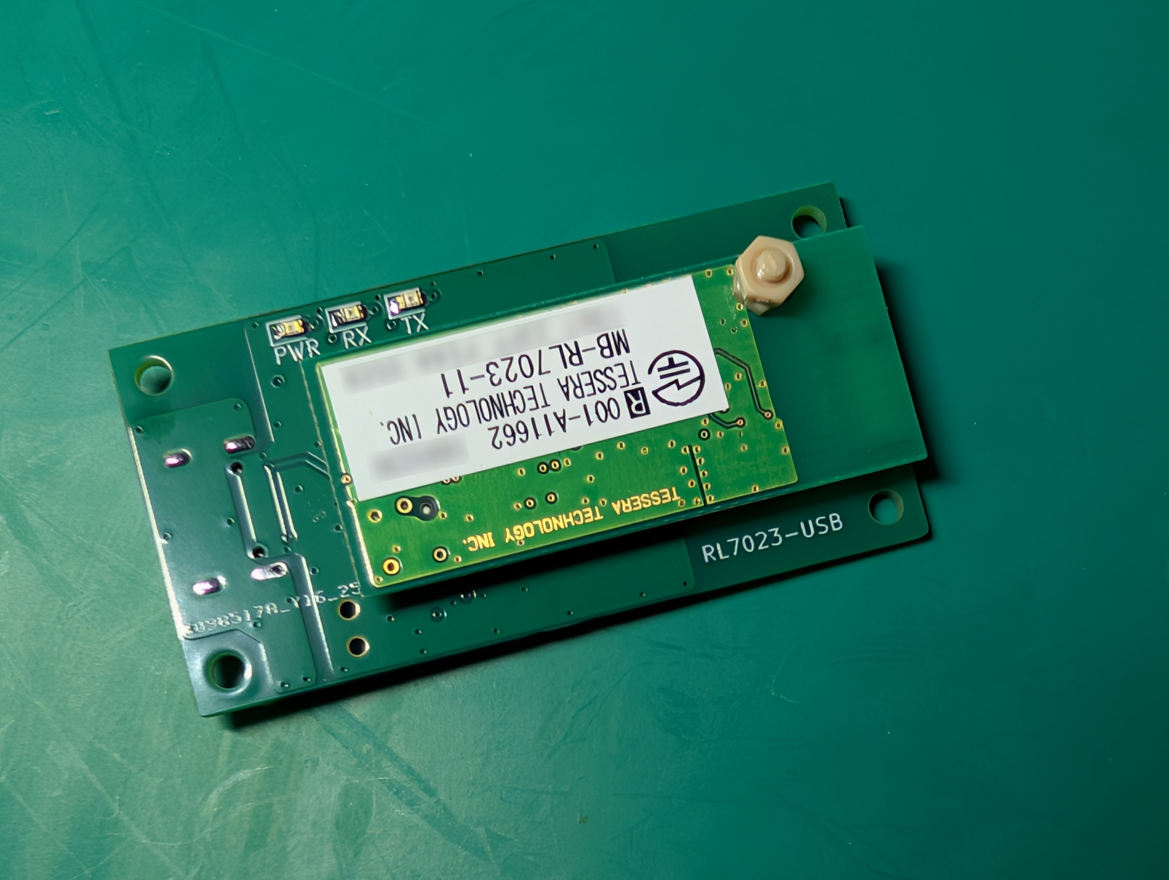
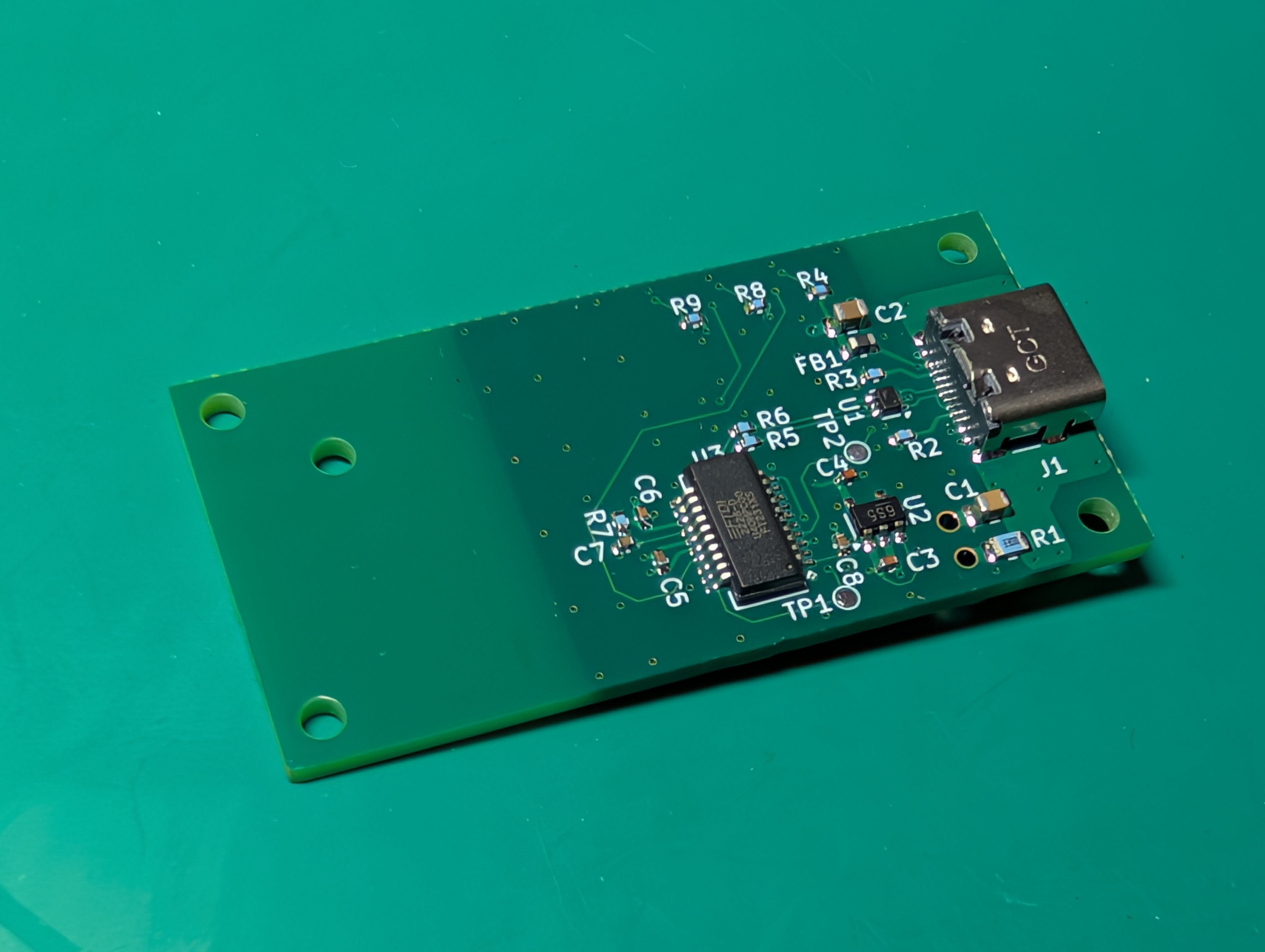
経験則上、この Wi-SUN モジュールを扱うためのソフトウェア・ライブラリを再起動したときの状態管理が難しいため、シリアルポートの (再) オープン時にモジュールをリセットするようにしました。
具体的には DTR が LOW レベルとなる際、Wi-SUN モジュールの RESET ピンも瞬間的に LOW レベルとなるようにしています。
このリセットが不要な場合には、C8 を非実装としてください。
RX・TX シルクは、この基板から USB 側に見たものです。
USB ホストから Wi-SUN モジュールへの命令送信時は RX LED が点滅し、それに対する Wi-SUN モジュールからの応答時には TX LED が点滅します。
MIT License
See LICENSE for more details.
| Qty | Value | Footprint | References |
|---|---|---|---|
| 5 | M2 Hole | MountingHole:MountingHole_2.2mm_M2 | H1, H2, H3, H4, H5 |
| 4 | 0.1u | Capacitor_SMD:C_0402_1005Metric | C5, C6, C7, C8 |
| 2 | 1u | Capacitor_SMD:C_0402_1005Metric | C3, C4 |
| 2 | 27 | Resistor_SMD:R_0402_1005Metric | R5, R6 |
| 2 | 5.1k | Resistor_SMD:R_0402_1005Metric | R2, R3 |
| 2 | TestPoint | TestPoint:TestPoint_Pad_D1.0mm | TP1, TP2 |
| 1 | 0.1u | Capacitor_SMD:C_0805_2012Metric | C1 |
| 1 | 10k | Resistor_SMD:R_0402_1005Metric | R7 |
| 1 | 10u | Capacitor_SMD:C_0805_2012Metric | C2 |
| 1 | 2.4k | Resistor_SMD:R_0402_1005Metric | R4 |
| 1 | 270 | Resistor_SMD:R_0402_1005Metric | R9 |
| 1 | 300 | Resistor_SMD:R_0402_1005Metric | R8 |
| 1 | 330 | Resistor_SMD:R_0805_2012Metric | R1 |
| 1 | BLM18PG471SN1D | Inductor_SMD:L_0603_1608Metric | FB1 |
| 1 | DF12NB(3.0)-20DS-0.5V(51) | RL7023-USB:Hirose_DF12NB(3.0)-20DS-0.5V(51)_2x10-P0.5mm | J2 |
| 1 | FT231XS | Package_SO:SSOP-20_3.9x8.7mm_P0.635mm | U3 |
| 1 | LTST-C190EKT | LED_SMD:LED_0603_1608Metric | D2 |
| 1 | LTST-C190GKT | LED_SMD:LED_0603_1608Metric | D3 |
| 1 | LTST-C190TBKT | LED_SMD:LED_0603_1608Metric | D1 |
| 1 | MIC5365-3.3YD5 | Package_TO_SOT_SMD:TSOT-23-5 | U2 |
| 1 | USB4105-GF-A | Connector_USB:USB_C_Receptacle_GCT_USB4105-xx-A_16P_TopMnt_Horizontal | J1 |
| 1 | USBLC6-2P6 | Package_TO_SOT_SMD:SOT-666 | U1 |

Brazil-L/Lumeward-OpenSource
Open-source Lumeward firmware and development tools

AkilaA25/Spoilage-Monitor_PCB
Battery-powered PCB that detects food spoilage in a fridge using a BME680 (VOC/humidity) and SCD40 (CO₂) sensor pair, an MSP430FR2355 MCU, and an IoT module header for phone connectivity.

lucadaloia/MSP430-LDR_ECE492
This project involved the design and manufacturing of a microcontroller-based system focused on analog signal acquisition and real-time user interaction.


It measures 50 × 25 mm and has 4 copper layers, 1.6 mm thick.
33 parts, built around the FT231XS-R, MIC5365-3.3YD5-TR, USBLC6-2P6 and DF12NB(3.0)-20DS-0.5V(51). The full list of its parts is on this page, with links to each part's symbol and footprint where PCBKit's library has them.
From the yuta2k/RL7023-USB repository on GitHub, at the commit this page was made from: the board is kicad/RL7023-USB.kicad_pcb and its schematic kicad/RL7023-USB.kicad_sch. PCBKit opens the board in the browser, with nothing to install.
Its repository publishes it under the MIT licence: you may reuse it on that licence's terms (keep the author's notice, and for a copyleft licence share your changes alike).