4 layers42.9 × 16 mm

 yuta2k/561SmartCard-USB
スマートカード互換モジュールを CCID 互換カードリーダに変換する基板
561SmartCard USB is an open-source printed circuit board by yuta2k, from the yuta2k/561SmartCard-USB repository on GitHub, published under the MIT licence. It is a 4-layer board of 30 × 45 mm with 33 parts on 26 nets, routed with 180 tracks and 75 vias.
It is built around the SEC1110-A5-02, USBLC6-2P6 and LTST-C190GKT, with the USB4105-GF-A and ZX60-B-5S(31) among its other parts. Its parts include 8 capacitors, 7 resistors, 4 connectors, 2 ICs and 1 diode.


スマートカード (ISO/IEC 7816) 互換モジュールを USB Type-C デバイスとして扱うための基板です。
USB-スマートカードブリッジ IC 「SEC1110」を採用しており、CCID 準拠のスマートカードリーダとして動作します。
スマートカード互換モジュールは、USB micro-B または DIP (8 ピン) の 2 種類に対応します。
DIP 形状のものは実物での確認を行っていないため、嵌合・動作しない可能性があります。
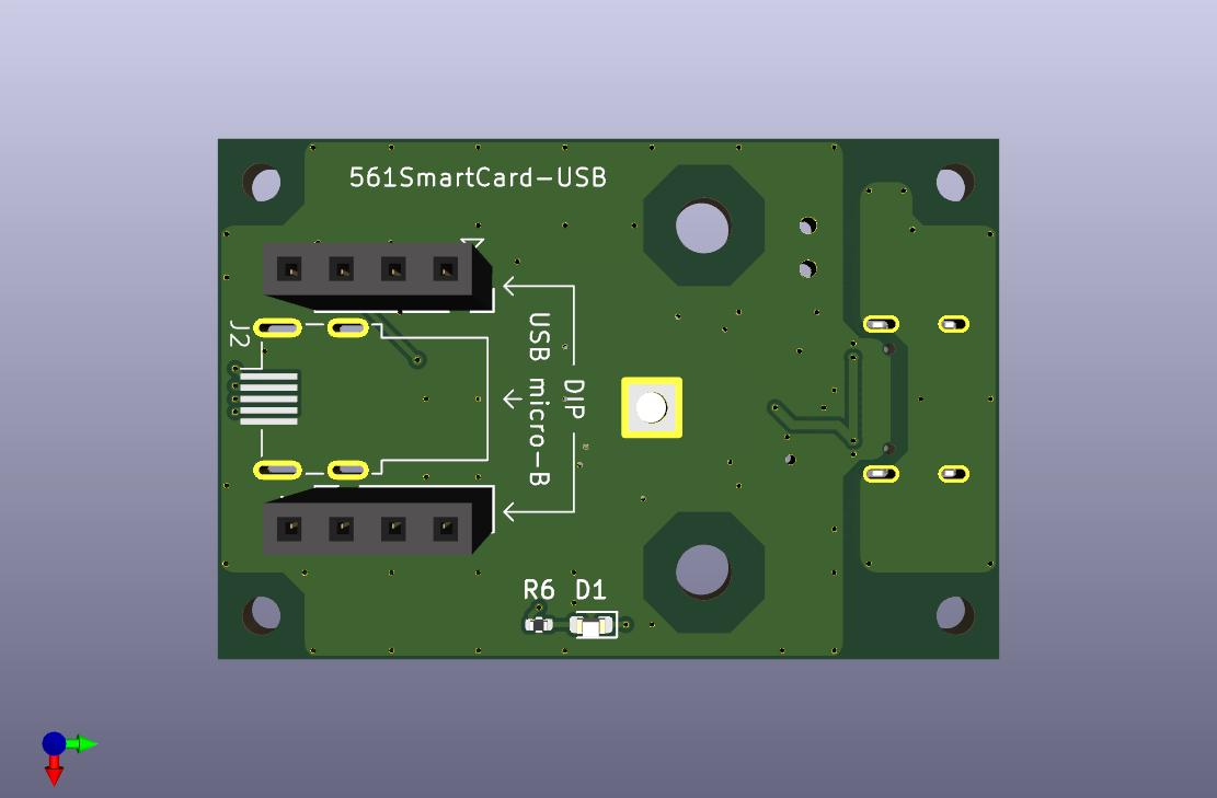
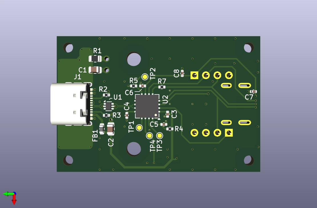
△ が 1 番ピンです (見切れていますが、画像 1 枚目右上)。
ここから反時計周りに 2, 3, ... 8 番ピンとなります。
MIT License
See LICENSE for more details.
| Qty | Value | Footprint | References |
|---|---|---|---|
| 4 | M2 Hole | MountingHole:MountingHole_2.2mm_M2 | H3, H4, H5, H6 |
| 4 | TestPoint | TestPoint:TestPoint_Pad_D1.0mm | TP1, TP2, TP3, TP4 |
| 3 | 0.1u | Capacitor_SMD:C_0402_1005Metric | C5, C7, C8 |
| 3 | 1u | Capacitor_SMD:C_0402_1005Metric | C3, C4, C6 |
| 2 | 5.1k | Resistor_SMD:R_0402_1005Metric | R2, R3 |
| 2 | M3 Hole | MountingHole:MountingHole_3.2mm_M3 | H1, H2 |
| 2 | PinSocket_01x04 | Connector_PinSocket_2.54mm:PinSocket_1x04_P2.54mm_Vertical | J3, J4 |
| 1 | 0 | Resistor_SMD:R_0402_1005Metric | R5 |
| 1 | 0.1u | Capacitor_SMD:C_0805_2012Metric | C1 |
| 1 | 100k | Resistor_SMD:R_0402_1005Metric | R4 |
| 1 | 10u | Capacitor_SMD:C_0805_2012Metric | C2 |
| 1 | 33 | Resistor_SMD:R_0402_1005Metric | R7 |
| 1 | 330 | Resistor_SMD:R_0805_2012Metric | R1 |
| 1 | 620 | Resistor_SMD:R_0402_1005Metric | R6 |
| 1 | BLM18PG471SN1D | Inductor_SMD:L_0603_1608Metric | FB1 |
| 1 | LTST-C190GKT | LED_SMD:LED_0603_1608Metric | D1 |
| 1 | SEC1110-A5-02 | 561SmartCard-USB:QFN-16-1EP_5x5mm_P0.8mm_EP2.7x2.7mm | U2 |
| 1 | USB4105-GF-A | Connector_USB:USB_C_Receptacle_GCT_USB4105-xx-A_16P_TopMnt_Horizontal | J1 |
| 1 | USBLC6-2P6 | Package_TO_SOT_SMD:SOT-666 | U1 |
| 1 | ZX60-B-5S(31) | 561SmartCard-USB:USB_Micro-B_Plug_Hirose_ZX60-B-5S(31) | J2 |


CopperPilot/copper-pilot-cli
CopperPilot in your terminal: a thin, open-source client for CopperPilot electronics design agent, the best AI for PCB Design.

antmicro/oculink-pcie-adapter
PCB design which converts an OCuLink connector into x16 PCIe slot

antmicro/ict-baseboard
PCB design for implementing In-Circuit Testing of other PCBs via an USB-enabled host

antmicro/job-storage-expansion
This project contains open hardware design files for an expansion board compatible with Antmicro's Jetson Orin Baseboard.


DhaDylan/esp32c3-direction-finding
An ESPARGOS-style 2-row × 4-column phased array, built to see how the scaled-up board would look. This is not a manufacturable design.
It measures 30 × 45 mm and has 4 copper layers, 1.6 mm thick.
33 parts, built around the SEC1110-A5-02, USBLC6-2P6, LTST-C190GKT and USB4105-GF-A. The full list of its parts is on this page, with links to each part's symbol and footprint where PCBKit's library has them.
From the yuta2k/561SmartCard-USB repository on GitHub, at the commit this page was made from: the board is kicad/561SmartCard-USB.kicad_pcb and its schematic kicad/561SmartCard-USB.kicad_sch. PCBKit opens the board in the browser, with nothing to install.
Its repository publishes it under the MIT licence: you may reuse it on that licence's terms (keep the author's notice, and for a copyleft licence share your changes alike).