
2 layers34 × 50 mm

 york-fs/bms-segment
Battery Management System Segment
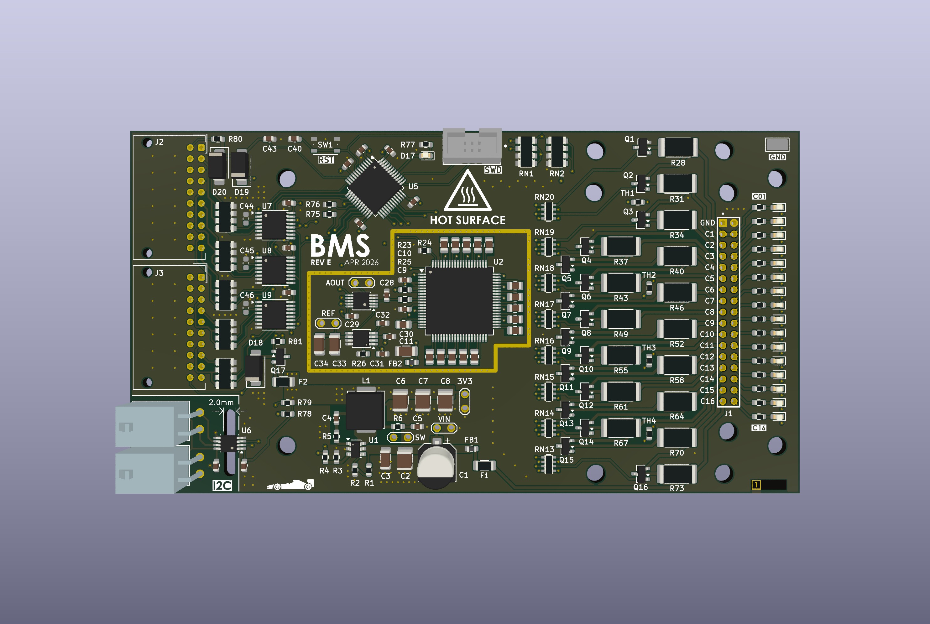
Bms segment is an open-source printed circuit board by york-fs, from the york-fs/bms-segment repository on GitHub. It is a 4-layer board of 120 × 65 mm with 206 parts on 240 nets, routed with 1,594 tracks and 537 vias.
It is built around the ADUM1252AWA+, MAX14921ECS+ and IRLML0060, with the BYG20J and BSS84 among its other parts. Its parts include 53 resistors, 49 capacitors, 20 diodes, 17 transistors and 9 ICs. It belongs with the power boards and the STM32 boards of this library.


The BMS segment board is part of the car's distributed BMS design. It connects to a series string of up to 16 cells and connects over an isolated I2C interface to the BMS master board to transfer cell voltage and temperature measurements.
Latest Release Interactive BOM
A recursive clone must be used to download the kicad-library repository:
git clone --recursive https://github.com/york-fs/bms-segment.git| Qty | Value | Footprint | References |
|---|---|---|---|
| 17 | 330 | Resistor_SMD:R_0603_1608Metric | R29, R32, R35, R38, R41, R44, R47, R50, R53, R56, R59, R62, R65, R68, R71, R74 +1 |
| 17 | LED_Small | LED_SMD:LED_0603_1608Metric | D1, D2, D3, D4, D5, D6, D7, D8, D10, D11, D12, D13, D14, D15, D16, D17 +1 |
| 16 | 1u | Capacitor_SMD:C_0805_2012Metric | C12, C13, C14, C15, C16, C17, C18, C19, C20, C21, C22, C23, C24, C25, C26, C27 |
| 16 | 20 | Resistor_SMD:R_2512_6332Metric | R28, R31, R34, R37, R40, R43, R46, R49, R52, R55, R58, R61, R64, R67, R70, R73 |
| 16 | IRLML0060 | Package_TO_SOT_SMD:SOT-23 | Q1, Q2, Q3, Q4, Q5, Q6, Q7, Q8, Q9, Q10, Q11, Q12, Q13, Q14, Q15, Q16 |
| 13 | 10k | Resistor_SMD:R_0603_1608Metric | R23, R24, R26, R75, R76, R78, R79, R80, R81, TH1, TH2, TH3, TH4 |
| 12 | 10k | Resistor_SMD:R_Array_Convex_4x1206 | RN1, RN2, RN3, RN4, RN5, RN6, RN7, RN8, RN9, RN10, RN11, RN12 |
| 12 | 1u | Capacitor_SMD:C_0603_1608Metric | C9, C10, C32, C35, C36, C37, C38, C39, C43, C47, C48, C49 |
| 11 | MountingHole | MountingHole:MountingHole_3.2mm_M3 | H1, H2, H3, H4, H5, H6, H7, H8, H9, H10, H11 |
| 8 | 3k | Resistor_SMD:R_Array_Concave_4x0603 | RN13, RN14, RN15, RN16, RN17, RN18, RN19, RN20 |
| 7 | 100n | Capacitor_SMD:C_0603_1608Metric | C4, C29, C30, C31, C40, C41, C42 |
| 5 | TestPoint_2Pole | yfs:TestPoint_2Pads_Pitch2.54mm_Drill1.0mm | TP1, TP2, TP3, TP4, TP5 |
| 4 | SolderJumper_2_Open | Jumper:SolderJumper-2_P1.3mm_Open_RoundedPad1.0x1.5mm | JP1, JP2, JP3, JP4 |
| 3 | 1n | Capacitor_SMD:C_0603_1608Metric | C44, C45, C46 |
| 3 | 22u | Capacitor_SMD:C_1210_3225Metric | C6, C7, C8 |
| 3 | 74LV4051A | Package_SO:TSSOP-16_4.4x5mm_P0.65mm | U7, U8, U9 |
| 3 | BYG20J | Diode_SMD:D_SMA | D18, D19, D20 |
| 2 | 100n | Capacitor_SMD:C_1206_3216Metric | C3, C11 |
| 2 | 10u | Capacitor_SMD:C_1206_3216Metric | C33, C34 |
| 2 | Conn_01x04 | yfs:MolexMicrofitPlus2x2-RA | J4, J5 |
| 2 | Conn_02x10_Odd_Even | Connector_JST:JST_PUD_S20B-PUDSS-1_2x10_P2.00mm_Horizontal | J2, J3 |
| 2 | LOGO | LOGO | G***, G**** |
| 2 | Polyfuse | Resistor_SMD:R_1206_3216Metric | F1, F2 |
| 1 | 100p | Capacitor_SMD:C_0603_1608Metric | C28 |
| 1 | 10M | Resistor_SMD:R_0603_1608Metric | R1 |
| 1 | 220 | Inductor_SMD:L_0603_1608Metric | FB2 |
| 1 | 220 | Resistor_SMD:R_0603_1608Metric | R25 |
| 1 | 22u | Inductor_SMD:L_Vishay_IHLP-2525 | L1 |
| 1 | 22u | Capacitor_SMD:CP_Elec_6.3x7.7 | C1 |
| 1 | 24k | Resistor_SMD:R_0603_1608Metric | R3 |
| 1 | 2u2 | Capacitor_SMD:C_1210_3225Metric | C2 |
| 1 | 390k | Resistor_SMD:R_0603_1608Metric | R2 |
| 1 | 600 | Inductor_SMD:L_0603_1608Metric | FB1 |
| 1 | 6R8 | Resistor_SMD:R_0603_1608Metric | R5 |
| 1 | 75k | Resistor_SMD:R_0603_1608Metric | R4 |
| 1 | ? | Resistor_SMD:R_0603_1608Metric | R6 |
| 1 | ? | Capacitor_SMD:C_0603_1608Metric | C5 |
| 1 | ADuM1252 | Package_SO:MSOP-8_3x3mm_P0.65mm | U6 |
| 1 | BSS84 | Package_TO_SOT_SMD:SOT-23 | Q17 |
| 1 | Conn_01x06 | yfs:IDC-Connector-2x3 | J6 |
| 1 | Conn_02x17_Counter_Clockwise | yfs:SAMTEC_TW-17-03-F-D-275-090 | J1 |
| 1 | G*** | kibuzzard-69D2F3F3 | kibuzzard-69D2F3F3 |
| 1 | G*** | kibuzzard-69EF73A7 | kibuzzard-69EF73A7 |
| 1 | G*** | kibuzzard-69D1B272 | kibuzzard-69D1B272 |
| 1 | LMR516xx | Package_TO_SOT_SMD:SOT-23-6 | U1 |
| 1 | MAX11163 | Package_SO:MSOP-10_3x3mm_P0.5mm | U3 |
| 1 | MAX14921 | Package_QFP:TQFP-80_12x12mm_P0.5mm | U2 |
| 1 | REF61xx | Package_SO:VSSOP-8_3x3mm_P0.65mm | U4 |
| 1 | STM32F103C8Tx | Package_QFP:LQFP-48_7x7mm_P0.5mm | U5 |
| 1 | SW_Push | Button_Switch_SMD:SW_Push_1P1T_NO_Vertical_Wuerth_434133025816 | SW1 |
| 1 | TestPoint | TestPoint:TestPoint_Keystone_5019_Miniature | TP6 |

sashkoBeats/Lithium-Battery-Research-Rig
University project development of a rig for lithium battery testing and research.


BlockWorker/ModularAudio
Compact, modular, versatile, hi-fi audio system concept.


Ibrahimk298/BudgetEIS
Files for the "Open-source impedance spectroscopy for in-incubator bio-monitoring" Project

york-fs/rear-distribution
The rear distribution board is the central board of the LVS. It provides fusing for all other LVS components and interfaces with the front, TSAC, and TS box distribution boards, as well as the inverter via AMPSEAL…


Solderingironspb/ModbusRTU_Master_MQTT_Gateway
Данное устройство выступает мастером сети ModbusRTU. Обменивается данными с подчиненными устройствами (до 247 устройств на линии RS485).
It measures 120 × 65 mm and has 4 copper layers, 1.61 mm thick.
206 parts, built around the ADUM1252AWA+, MAX14921ECS+, IRLML0060 and BYG20J. The full list of its parts is on this page, with links to each part's symbol and footprint where PCBKit's library has them.
From the york-fs/bms-segment repository on GitHub, at the commit this page was made from: the board is bms_segment.kicad_pcb and its schematic balance.kicad_sch. PCBKit opens the board in the browser, with nothing to install.
Its repository states no licence, so its author keeps all rights: ask york-fs before reusing the design.