Skip to the content
2 layers309.6 × 76.2 mmQ9-Chimera, the printed circuit board in 3D

A drop-in, multi-layout (ortho/row/alpha stagger) PCB with numpad for Keychron Q9

Size
309.6 × 76.2 mm
Copper layers
2
Thickness
1.6 mm
Parts
201
Nets
117
Pads
1,163
Tracks, vias
1,131, 118
Pours
1
Routed
Yes
KiCad
KiCad 8.0 (file 20240108)
Created
28 May 2024
Updated
22 Oct 2024

Overview

Q9-Chimera is an open-source printed circuit board by xommmmmmmm, from the xommmmmmmm/QueueNineChimera repository on GitHub. It is a 2-layer board of 309.6 × 76.2 mm with 201 parts on 117 nets, routed with 1,131 tracks and 118 vias.

It is built around the RP2040, W25Q128JVSIQ and SRV05-4. Its parts include 63 diodes, 16 capacitors, 13 switches, 7 resistors and 4 ICs. It belongs with the RP2040 boards of this library.

Main components

3

README

README.md

Q9 Chimera & Limousine

Q9 Chimera & Limousine are RP2040-based, drop-in, multi-layout replacement PCBs for Keychron Q9. Chimera supports ortholinear layout with central or right-hand numpad, and traditional row-stagger with right hand numpad. Limousine supports row and alpha stagger, with support for 2.25u/2.75u "Alice" bars and right-hand numpad.

Both versions support up to two independent EC11 rotary encoders in the separated key positions, and a plethora of bottom-row options.

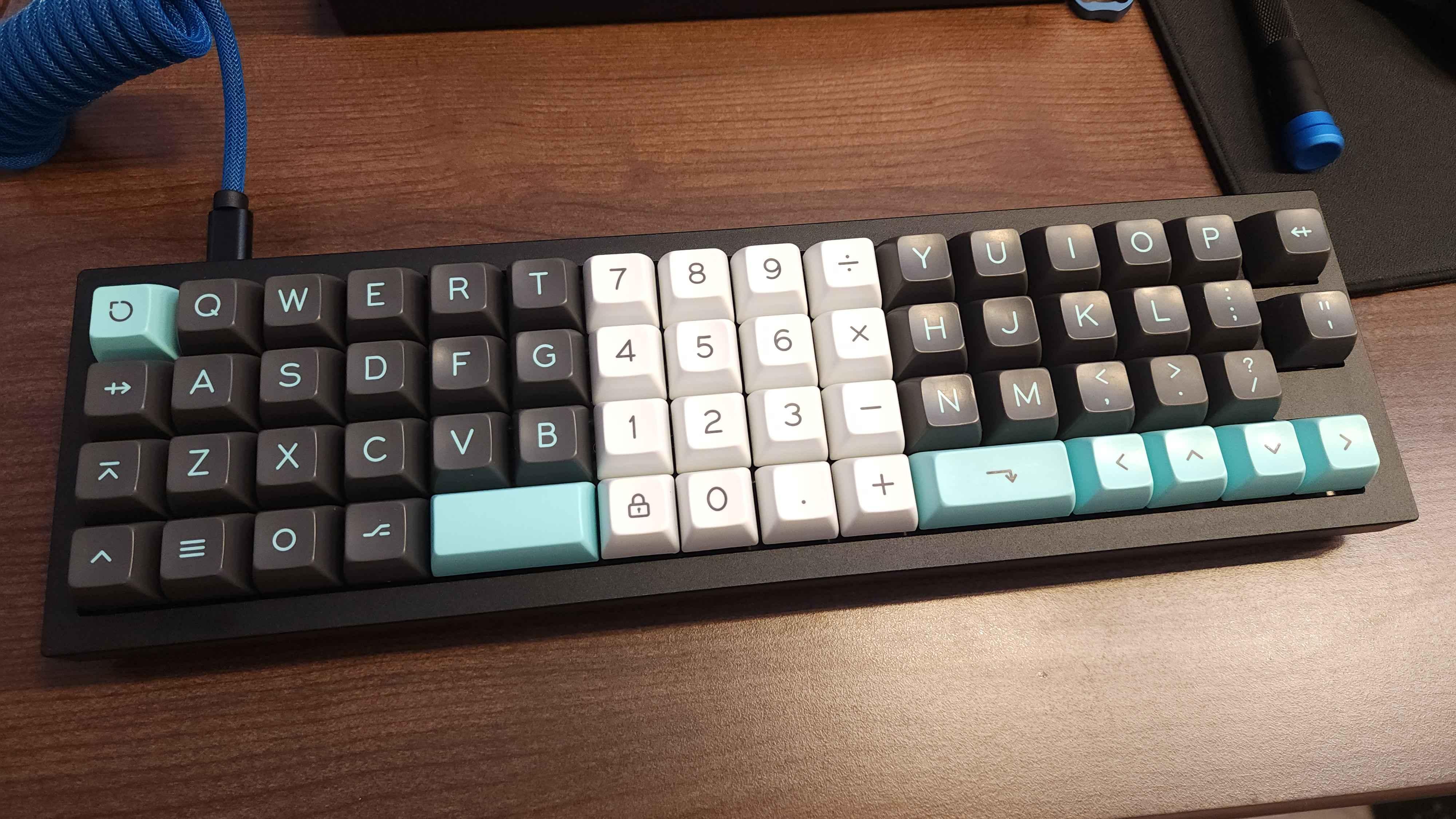
Q9 Chimera Ortho xomm's split ortho build

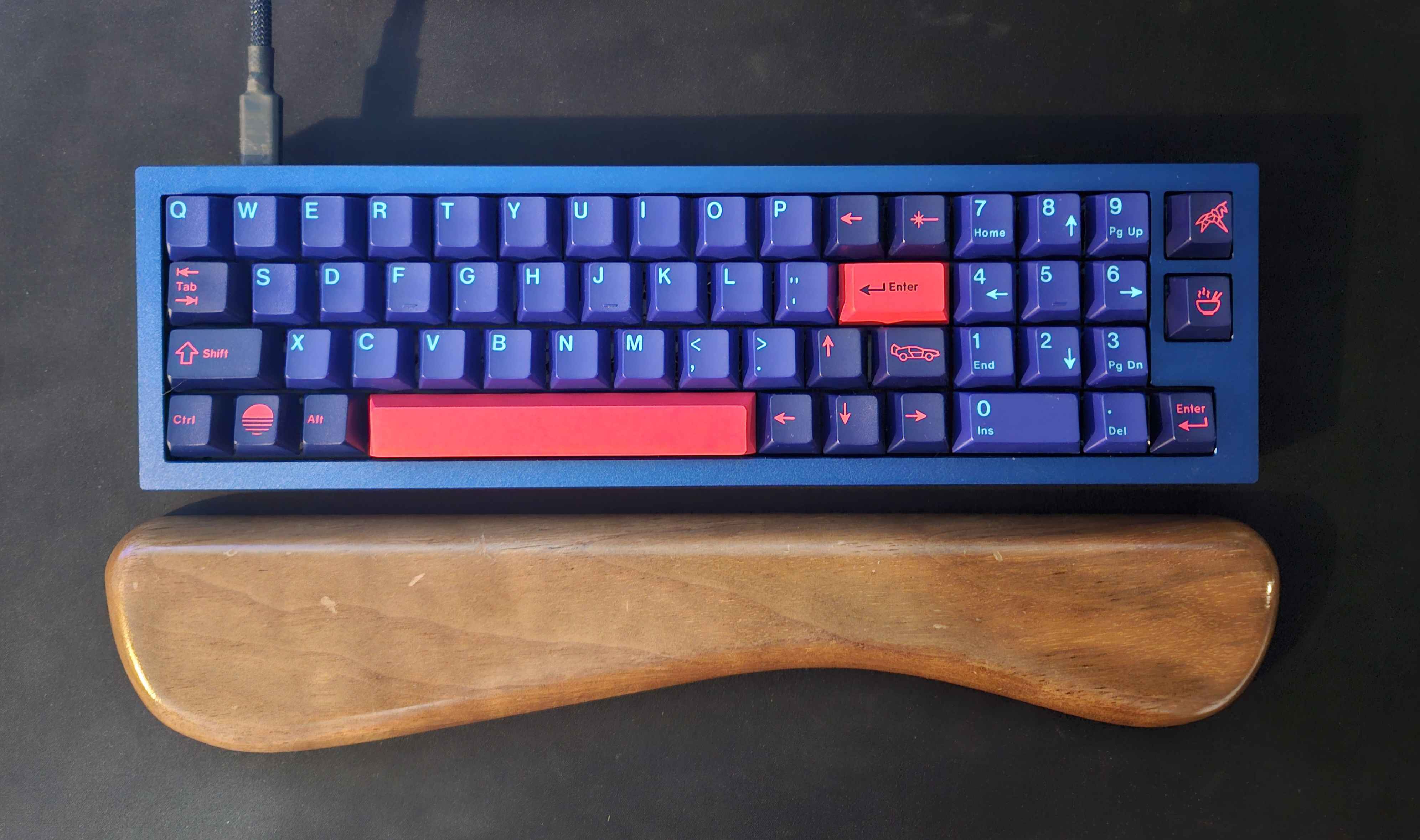
Q9 Chimera Row Stagger baconspoon's row-staggered build

Hardware

  • Keyboard Maintainer: xomm and baconspoon
  • Hardware Supported: Keychron Q9, Keychron Q9 Plus cases with Q9 Chimera PCB
  • Hardware Availability: Case from Keychron, Open-source PCB orderable from JLCPCB using provided production files in their respective subfolders. Production files should be orderable as-is and have been used successfully for PCBA, but no guarantees or warranties are made.

This project is not affiliated with or endorsed by Keychron or JLCPCB.

Build Guide

Disassembly:

  1. If you have keycaps on the board, remove them before disassembly to avoid scratching them against the case.
  2. Flip the board upside down and unscrew the six H2.5 screws on the bottom case to remove it.
  3. Disconnect the JST connector from the original board
  4. Lift the assembly out by lifting from the bottom (spacebar side) first, then pull it out from under the daughterboard. Take care not to lose the 3 plastic caps from the pegs on the top case.

Test the new PCB:

  1. Insert 2 switches in the top left for unlocking the board.
  2. Connect the JST from the daughterboard to the new board.
  3. Taking care to not short any board components on the top case, connect the USB-C to your PC.
  4. Open https://vial.rocks/ to validate that it is detected.
  5. Open the matrix tester and use tweezers or a switch puller to check sockets.
  6. Disconnect USB-C once done, then disconnect the JST.

PCB Assembly:

  1. If you have a barebones PCB and/or want to add EC11 encoder(s), now is the time to solder.
    1. If you are not using encoder(s), and you originally purchased the Q9 with one, remove the PH1 screws holding in the encoder blocker from the top case.
  2. Add any PCB-mounted stabilizers you will be using. If your switches have minimal wobble, you generally won't need 2u stabilizers.
    1. Limousine note: If you chose to have Mill-Max sockets soldered for 3u spacebars, you will need to desolder one of the Kailh hotswap sockets to access a 3u stabilizer hole. Conversely, the 3u Mill-Max sockets sit under the stabilizers of other footprints, so you may want to add pads under your stabilizers to reduce the bottom-out noise.

Plate Assembly:

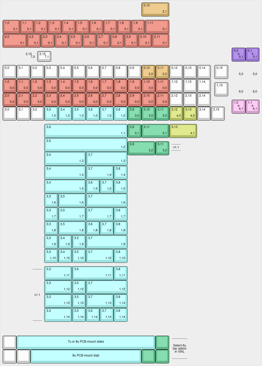
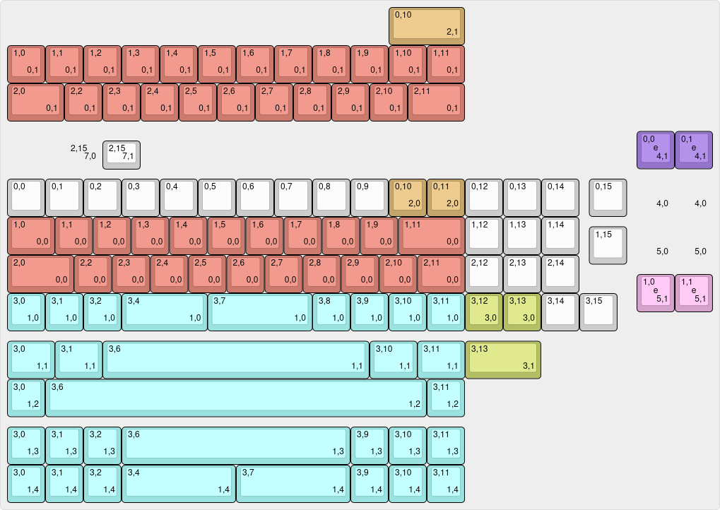
  1. When inserting switches, support the hotswap socket from the back to avoid accidental damage in case of misalignment. Reference the KLE for your desired layout if unsure which footprints to use.
  2. To align the plate, place switches around the border of the plate and a few in the top row, then assemble the plate to the PCB.
  3. To minimize plate flex when inserting switches, fill out the remaining switches from right to left, top to bottom.
  4. If you will be reusing the original foam gaskets, remove them carefully by picking at one side until all the adhesive is lifted, then slowly peel it off the plate.
  5. If you will be using the included gaskets from the kit, they are unfortunately short, but will function and sound pretty much the same.
    1. You can choose to use them as-is and stick them in the middle, or cut them in half and stick them on the edges.
  6. Apply the gaskets on both sides of the plate (eight total), using tweezers is recommended.

Case Assembly:

  1. Insert the assembly into the top case, putting the top under the daughterboard first, then aligning the mounting holes on the plate with the pegs in the top case. Pay attention to the six screw posts since they might catch on their cutouts in plate a bit. There might be a little bit of friction at first but it will seat once everything is aligned, heavy force is not required.
  2. Tape modding the bottom of the PCB or the inside of the bottom case, either with the stock cardboard adhesive and/or 3M painter's tape is highly recommended. This will prevent unlikely but possible shorts from bottoming out the PCB on aftermarket gaskets if you press hard.
  3. Close the bottom case, add keycaps, set up your layout in Vial.
    1. In Vial, use the Layouts tab to select the physical layout options you want. For the 8u/10u spacebar option on Chimera v1.1, select the first 6u bar option and simply leave the unused keys blank.
  4. Enjoy! (And maybe send a pic of your completed build in the mini-GB channel on the 40% Keyboards Discord server!)

Firmware

PCBs purchases from the mini-GB are pre-flashed. Vial firmware source can be found here. Pre-compiled firmware can be found here.

Q9 Chimera keymap options

All sockets for all layout options can be populated during PCB assembly, including the ones under the encoders.

Q9 Chimera v1.1 keymap options

Q9 Limousine v1.0 keymap options

Options

Q9 Chimera keymap option names

The images at the top use the following options:

  • xomm's split ortho layout:
    • Spacebar option 8: 1-2-1-1-1
    • Split Ortho, Right 2u Spacebar
  • baconspoon's row-staggered layout:
    • Row Stagger
    • Spacebar option 2: 6 (off-center, flipped)
    • Right Numpad, 2u Zero

The default keymap is provided as barebones due to the number of possible layouts, and should be edited as desired. Remember to export your .vil from Vial GUI once satisfied for safekeeping.

Credits and helpful things

  • Big thanks to baconspoon for validating the design, contributing plate/edge cuts, additional layouts, and a ton of other help.
  • Noah Kiser's TKL RP2040 PCB Design series
  • Joe Scotto's PCB Design series

Parts

201
QtyValueFootprintReferences
81MX_SW_HSPCM_marbastlib-mx:SW_MX_HS_CPG151101S11_1uMX10, MX11, MX12, MX13, MX14, MX15, MX17, MX18, MX19, MX20, MX21, MX22, MX23, MX24, MX25, MX26 +65
63D_Smallxomm:D_SOD-123_xommD1, D2, D10, D11, D12, D13, D14, D15, D16, D17, D18, D19, D20, D21, D22, D23 +47
8100nCapacitor_SMD:C_0402_1005MetricC4, C7, C8, C9, C13, C14, C15, C16
7MX_stab_2uPCM_marbastlib-mx:STAB_MX_2uS1, S2, S3, S4, S7, S8, S9
51uCapacitor_SMD:C_0402_1005MetricC1, C2, C3, C6, C11
5MX_SW_HSPCM_marbastlib-mx:SW_MX_HS_S_CPG151101S11_1uMX1, MX2, MX3, MX16, MX32
35.1kResistor_SMD:R_0402_1005MetricR3, R4, R5
3MX_SW_HSPCM_marbastlib-mx:SW_MX_1uMX53, MX60, MX95
3MX_stab_3uPCM_marbastlib-mx:STAB_MX_3uS5, S6, S10
21kResistor_SMD:R_0402_1005MetricR6, R9
222pCapacitor_SMD:C_0402_1005MetricC10, C12
227Resistor_SMD:R_0402_1005MetricR7, R8
2MX_SW_HSPCM_marbastlib-mx:SW_MX_HS_CPG151101S11_1.75uMX79, MX80
2MX_SW_HSPCM_marbastlib-mx:SW_MX_HS_CPG151101S11_1.25uMX69, MX90
2RotaryEncoder_SwitchPCM_marbastlib-various:ROT_Alps_EC11E-SwitchSW1, SW2
2SW_PushButton_Switch_SMD:SW_SPST_TL3342BOOT1, RST1
110uCapacitor_SMD:C_0603_1608MetricC5
1Conn_01x05Connector_PinHeader_2.54mm:PinHeader_1x05_P2.54mm_VerticalJ3
1Conn_01x07Connector_JST:JST_SH_BM07B-SRSS-TB_1x07-1MP_P1.00mm_VerticalJ1
1Crystal_GND24Crystal:Crystal_SMD_3225-4Pin_3.2x2.5mmY1
1MX_stab_7810uPCM_marbastlib-mx:STAB_MX_10uS13
1RP2040Package_DFN_QFN:QFN-56-1EP_7x7mm_P0.4mm_EP3.2x3.2mmU3
1SRV05-4PCM_marbastlib-various:SOT-23-6-routableU2
1W25Q128JVSPackage_SO:SOIC-8_5.23x5.23mm_P1.27mmU4
1XC6206PxxxMRPackage_TO_SOT_SMD:SOT-23-3U1

Similar boards

  • 2 layers63.5 × 58 mmLatest, the printed circuit board in 3D

    Latest

    minipadKB/minipad

    The PCB and case files for the minipad, an RP2040-based 2-3-key keypad for the rhythm game osu!.

    39 parts52GPL-3.0
  • 2 layers224.4 × 97.8 mmKnobdeavour, the printed circuit board in 3D

    Knobdeavour

    ScatteredDrifter/Buran-Ortho

    A 39-key orthogonal keyboard with support for two knobs, based on a rp2040

    105 parts46
  • 2 layers253.3 × 113.3 mmCut slope, the printed circuit board in 3D

    Cut slope

    hazels-garage/cut-slope

    119 parts29
  • 2 layers344.7 × 123.6 mmSlime88, the printed circuit board in 3D

    Slime88

    zykrah/slime88

    A F13 TKL Multi-Layout Hotswap H88-Compat Type-C PCB

    243 parts29
  • 2 layers346.1 × 118.3 mmTKL VIDEO, the printed circuit board in 3D

    TKL VIDEO

    NCKiser/TKL_VIDEO

    233 parts17
  • 2 layers236.9 × 86.8 mmRaii020, the printed circuit board in 3D

    Raii020

    unspecworks/raii

    splay sweep with ferris

    233 parts17
  • 2 layers346.1 × 93.7 mmSifrl main pcb, the printed circuit board in 3D

    Sifrl main pcb

    ramonimbao/SpaceInvadersFRL

    An F-rowless TKL keyboard case, plate, and PCB that uses the HiTek Series 725 switches.

    177 parts15
  • 2 layers194.3 × 79 mmQez, the printed circuit board in 3D

    Qez

    IvoPo/qezberry

    115 parts14GPL-3.0

Questions

How big is the Q9-Chimera PCB?

It measures 309.6 × 76.2 mm and has 2 copper layers, 1.6 mm thick.

What parts does the Q9-Chimera use?

201 parts, built around the RP2040, W25Q128JVSIQ and SRV05-4. The full list of its parts is on this page, with links to each part's symbol and footprint where PCBKit's library has them.

Where can I download the Q9-Chimera KiCad files?

From the xommmmmmmm/QueueNineChimera repository on GitHub, at the commit this page was made from: the board is Q9-Chimera/Q9-Chimera-PCB/Q9-Chimera.kicad_pcb and its schematic Q9-Chimera/Q9-Chimera-PCB/Q9-Chimera.kicad_sch. PCBKit opens the board in the browser, with nothing to install.

Can I use the Q9-Chimera design in my own project?

Its repository states no licence, so its author keeps all rights: ask xommmmmmmm before reusing the design.