2 layers174 × 58 mm
Breakout 112pin Connector
rusefi/rusefi
rusefi - GPL internal combustion engine control unit
42 parts1.2k
 XcapeCodes/EOSAS
Embedded imaging system integrating ESP32-CAM, C/C++ firmware, a custom PCB, computer vision, and machine learning.
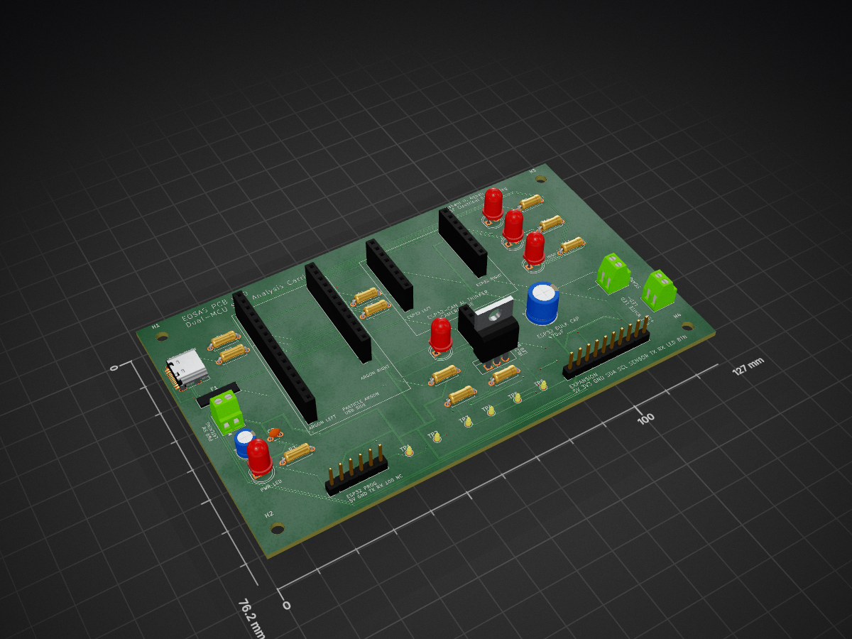
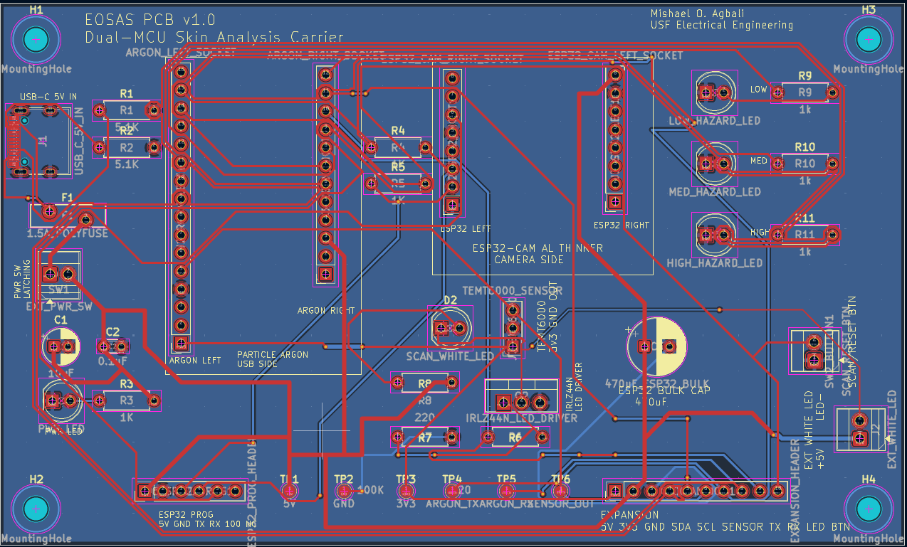
EOSAS PCB v1.0 is an open-source printed circuit board by XcapeCodes, from the XcapeCodes/EOSAS repository on GitHub, published under the MIT licence. It is a 2-layer board of 127 × 76.2 mm with 42 parts on 56 nets, routed with 439 tracks and 26 vias.
Its parts include 11 resistors, 9 connectors, 5 diodes, 3 capacitors and 2 switches. It belongs with the ESP32 and RISC-V boards of this library.
← Back to main EOSAS documentation
EOSAS PCB v1.0 is a custom dual-MCU carrier board designed to replace the breadboard wiring used in the original EOSAS prototype and consolidate the system electronics onto a dedicated PCB.
Design complete — fabrication and physical validation pending.
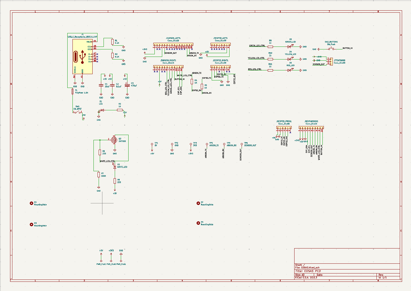
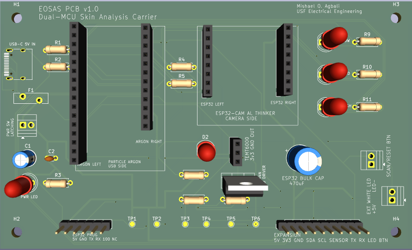
The Particle Argon serves as the primary hardware controller, managing user inputs, illumination, optical sensing, and hazard indicators. The ESP32-CAM handles image acquisition and communication with the EOSAS inference server.
The two controllers communicate through the PCB's dedicated interface, allowing the embedded hardware and image-processing pipeline to operate as one system.
EOSAS is an experimental engineering project and is not intended to provide medical diagnoses.
| Qty | Value | Footprint | References |
|---|---|---|---|
| 4 | MountingHole | MountingHole:MountingHole_3.2mm_M3 | H1, H2, H3, H4 |
| 3 | 1K | Resistor_THT:R_Axial_DIN0207_L6.3mm_D2.5mm_P7.62mm_Horizontal | R3, R4, R5 |
| 3 | 1k | Resistor_THT:R_Axial_DIN0207_L6.3mm_D2.5mm_P7.62mm_Horizontal | R9, R10, R11 |
| 2 | 220 | Resistor_THT:R_Axial_DIN0207_L6.3mm_D2.5mm_P7.62mm_Horizontal | R6, R8 |
| 2 | 5.1K | Resistor_THT:R_Axial_DIN0207_L6.3mm_D2.5mm_P7.62mm_Horizontal | R1, R2 |
| 1 | 0.1uF | Capacitor_THT:C_Disc_D3.0mm_W1.6mm_P2.50mm | C2 |
| 1 | 1.5A_POLYFUSE | Fuse:Fuse_Bourns_MF-RG500 | F1 |
| 1 | 100K | Resistor_THT:R_Axial_DIN0207_L6.3mm_D2.5mm_P7.62mm_Horizontal | R7 |
| 1 | 10uF | Capacitor_THT:CP_Radial_D5.0mm_P2.00mm | C1 |
| 1 | 3V3 | TestPoint:TestPoint_Pad_D1.5mm | TP3 |
| 1 | 470uF_ESP32_BULK | Capacitor_THT:CP_Radial_D8.0mm_P3.50mm | C3 |
| 1 | 5V | TestPoint:TestPoint_Pad_D1.5mm | TP1 |
| 1 | ARGON_LEFT_SOCKET | Connector_PinSocket_2.54mm:PinSocket_1x16_P2.54mm_Vertical | J2ARGON_LEFT1 |
| 1 | ARGON_RIGHT_SOCKET | Connector_PinSocket_2.54mm:PinSocket_1x12_P2.54mm_Vertical | J3ARGON_RIGHT1 |
| 1 | ARGON_RX | TestPoint:TestPoint_Pad_D1.5mm | TP5 |
| 1 | ARGON_TX | TestPoint:TestPoint_Pad_D1.5mm | TP4 |
| 1 | ESP32_CAM_LEFT_SOCKET | Connector_PinSocket_2.54mm:PinSocket_1x08_P2.54mm_Vertical | J3ESP32_LEFT1 |
| 1 | ESP32_CAM_RIGHT_SOCKET | Connector_PinSocket_2.54mm:PinSocket_1x08_P2.54mm_Vertical | J2ESP32_RIGHT1 |
| 1 | ESP32_PROG_HEADER | Connector_PinHeader_2.54mm:PinHeader_1x06_P2.54mm_Vertical | J6ESP32_PROG1 |
| 1 | EXPANSION_HEADER | Connector_PinHeader_2.54mm:PinHeader_1x10_P2.54mm_Vertical | J8EXPANSION1 |
| 1 | EXT_PWR_SW | TerminalBlock:TerminalBlock_Xinya_XY308-2.54-2P_1x02_P2.54mm_Horizontal | SW1 |
| 1 | EXT_WHITE_LED | TerminalBlock:TerminalBlock_Xinya_XY308-2.54-2P_1x02_P2.54mm_Horizontal | J2 |
| 1 | GND | TestPoint:TestPoint_Pad_D1.5mm | TP2 |
| 1 | HIGH_HAZARD_LED | LED_THT:LED_D5.0mm | D5 |
| 1 | IRLZ44N_LED_DRIVER | Package_TO_SOT_THT:TO-220-3_Vertical | Q2 |
| 1 | LOW_HAZARD_LED | LED_THT:LED_D5.0mm | D3 |
| 1 | MED_HAZARD_LED | LED_THT:LED_D5.0mm | D4 |
| 1 | PWR_LED | LED_THT:LED_D5.0mm | D1 |
| 1 | SCAN_RESET_BTN | TerminalBlock:TerminalBlock_Xinya_XY308-2.54-2P_1x02_P2.54mm_Horizontal | SW2_BUTTON1 |
| 1 | SCAN_WHITE_LED | LED_THT:LED_D5.0mm | D2 |
| 1 | SENSOR_OUT | TestPoint:TestPoint_Pad_D1.5mm | TP6 |
| 1 | TEMT6000_SENSOR | Connector_PinSocket_2.54mm:PinSocket_1x03_P2.54mm_Vertical | J7TEMT6000 |
| 1 | USB_C_5V_IN | Connector_USB:USB_C_Receptacle_HRO_TYPE-C-31-M-12 | J1 |
It measures 127 × 76.2 mm and has 2 copper layers, 1.6 mm thick.
42 parts. The full list of its parts is on this page, with links to each part's symbol and footprint where PCBKit's library has them.
From the XcapeCodes/EOSAS repository on GitHub, at the commit this page was made from: the board is PCB/EOSAS_PCB_v1.0.kicad_pcb and its schematic PCB/EOSAS_PCB_v1.0.kicad_sch. PCBKit opens the board in the browser, with nothing to install.
Its repository publishes it under the MIT licence: you may reuse it on that licence's terms (keep the author's notice, and for a copyleft licence share your changes alike).
rusefi/rusefi
rusefi - GPL internal combustion engine control unit


hackclub/sprig
🍃 Learn to code by making games in a JavaScript web-based game editor.

jamro/tiny-engineer
A small desktop robot that brings an AI coding assistant to life, physically acting out when it reads files, thinks, writes code, and finishes work.

hoglet67/RGBtoHDMI
Bare-metal Raspberry Pi project that provides pixel-perfect sampling of Retro Computer RGB/YUV video and conversion to HDMI

hackclub/OnBoard
💡 Join 1,000 teenagers and make your first PCB with a $100 grant!

