
2 layers18.5 × 11.1 mm
Switch
byrantech/laptop
anyon_e, a highly integrated, high end, open source laptop. Attempt the impossible.
6 parts4.3kMIT

 xavier-phillips/stepper-blinds-driver
An ultra-quiet NEMA 17 retrofit driver for beaded-chain roller blinds.
Stepper blinds driver is an open-source printed circuit board by xavier-phillips, from the xavier-phillips/stepper-blinds-driver repository on GitHub, published under the MIT licence. It is a 2-layer board of 48 × 46.6 mm with 6 parts on 26 nets, routed with 65 tracks and 58 vias.
Its parts include 1 capacitor and 1 connector. It belongs with the robots and motor control boards of this library.
An ultra-quiet NEMA 17 retrofit driver for beaded-chain roller blinds.
Xavier Phillips






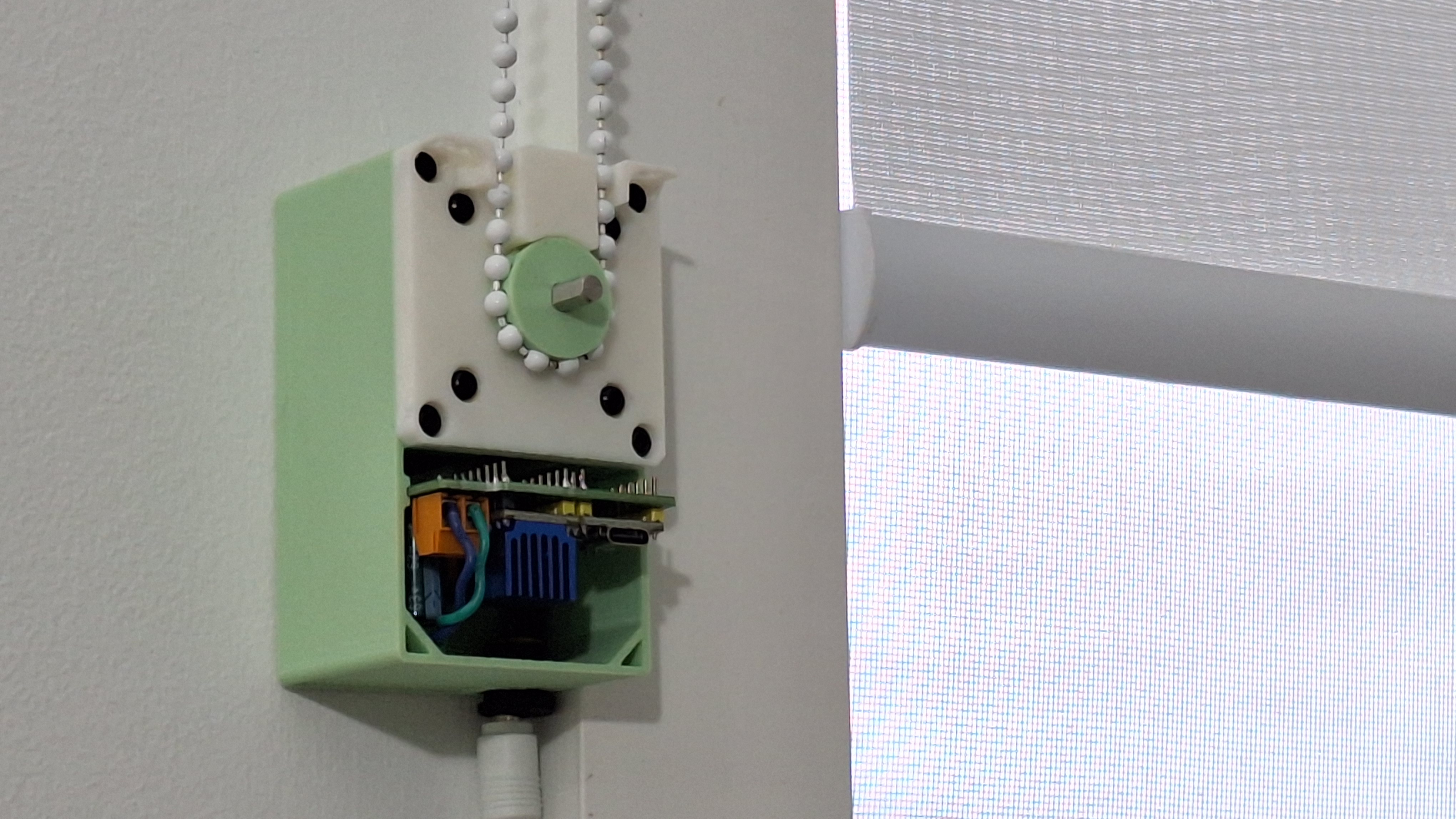 The stepper blinds driver with the top lid removed, showing the main sprocket and the custom PCB.
Opening blinds automatically has a range of benefits:
Commercial options have some limitations:
| Type | Personal project (no course/folio behind it) |
|---|---|
| Duration | Started ~30 June 2026, ongoing |
| Budget | $79.11 true project cost (target: <$100) |
| Mechanism | Beaded-chain actuation, positional control (e.g. set to 50%) |
| MCU / Control | ESP32-C6 Mini Dev Board (Serial CLI Firmware v1.0) |
| Motor / driver | NEMA 17 Stepper Motor (34mm, 1.5A) + TMC2209 V2.0 Stepper Driver |
| PCB | Custom 2-layer PCB for all electrical components |
| Mechanical CAD | Onshape |
| Manufacturing | 3D printing |
| Spec | Value |
|---|---|
| Required pulling force | 1.8kg (bucket-tested - see build log) |
| Noise target | <40dB (commercial cheap models are >50dB) |
| Travel range | Unlimited |
| Holding torque | N/A, designed for counterbalanced or friction-balanced household blinds |
| Power supply | 12V 3A 36W power supply |
| Ecosystem tested against | Google Home or Home Assistant (per scope - not yet tested) |
| Area | Skills and tools |
|---|---|
| Mechanical design | Onshape CAD - hot-swappable cog/sprocket mount for the beaded chain, compact enclosure |
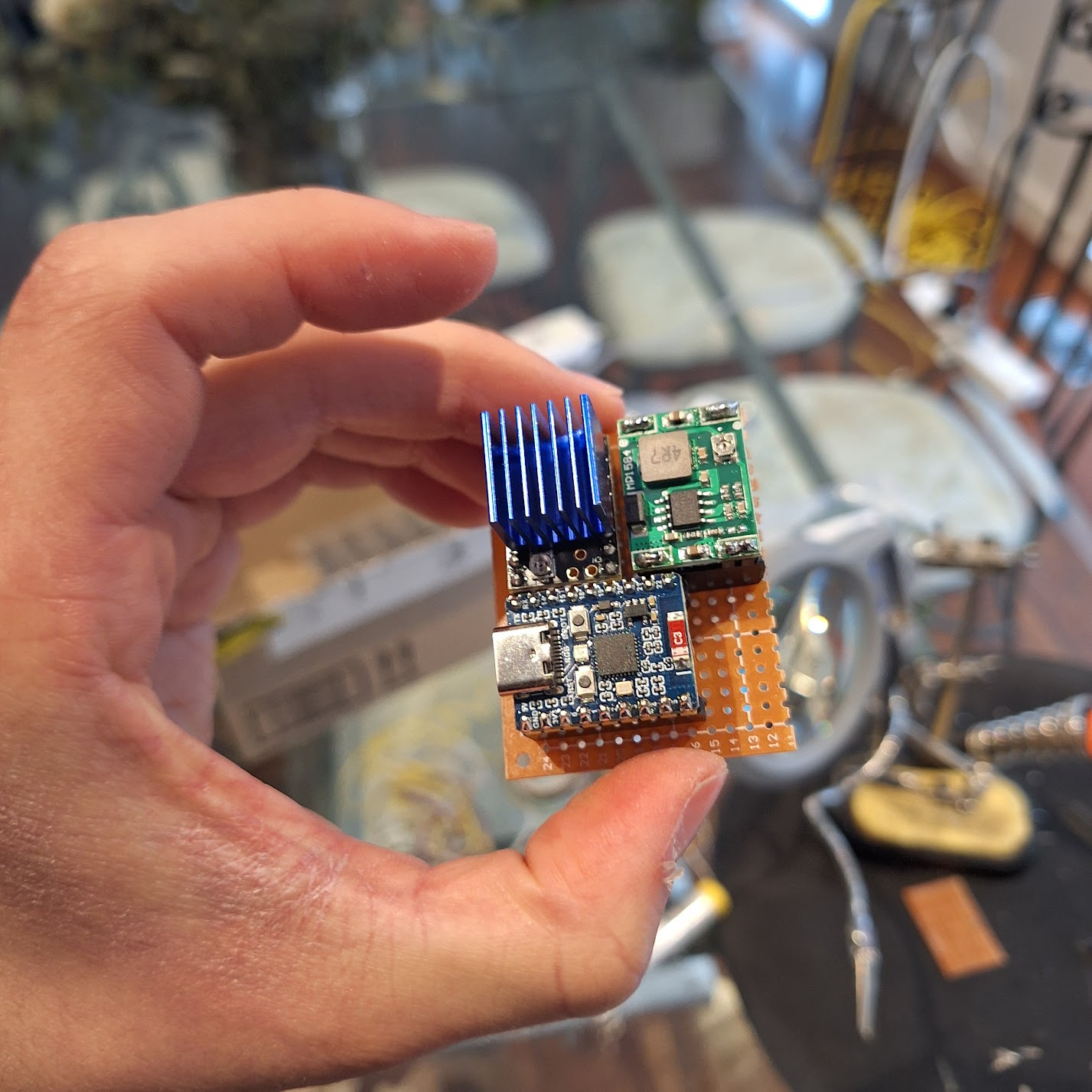
| PCB design | KiCad - custom two-layer PCB, manufactured by JLCPCB; the first prototype used off-the-shelf breakouts (TMC2209 driver module, MP1584EN buck converter) on a perfboard |
| Embedded programming | C++ / Arduino on ESP32 (Non-blocking stepper driver integration) |
| Smart home integration | Google Home or Home Assistant, for scheduled automations |
| Manufacturing | 3D printing |
| Decision | Options considered | Reasoning |
|---|---|---|
| Motor + driver | Ranked 10 motor setups against the <40dB noise / <$100 cost constraints (full comparison below); shortlisted NEMA 17 + TMC2209, JGY-370 Worm Gear Motor, NEMA 17 (5:1 Planetary Geared) + TMC2209 | This motor is extremely well documented and has a low noise level when paired with the TMC2209 controller. |
| PCB / prototyping approach | Off-the-shelf breakout modules (TMC2209 driver, MP1584EN buck converter) on a prototype board vs. a from-scratch custom PCB | V1 is on protoboard for now; custom PCB for final product is goal #7 |
| Button / enclosure interface | Minimal-none. The device is intended to be controlled wirelessly in the final iteration. Prototypes are controlled via serial CLI. | Buttons should be minimised for aesthetic (goal #5) |
The biggest constraints for the motor are the <40dB requirement and the cost (total cost <$100)
What impacts motor noise?
Overall, the magnitude of these sounds is also proportional to the RPM of the motor, so a slower RPM motor is ideal (and has the additional advantage of making the change in light level more gradual)
| Rank | Motor Setup | Category | Torque (Nm) | Max RPM | RPM Notes | Self-Locking | Approx. Noise Level (dB) | Dimensions (mm) | Volume (cm³) |
|---|---|---|---|---|---|---|---|---|---|
| 1 | NEMA 17 (Standard 42mm) + TMC2209 | Stepper | 0.40 | 400 | Variable | No | 38 | 42.3 x 42.3 x 40.0 | 71.57 |
| 2 | JGY-370 Worm Gear Motor (12V) | Brushed DC | 1.00 | 40 | Gearbox Fixed | Yes | 42 | 76.8 x 32.0 x 25.2 | 61.93 |
| 3 | NEMA 17 (5:1 Planetary Geared) + TMC2209 | Stepper | 1.50 | 80 | Variable | No | 43 | 42.3 x 42.3 x 61.3 | 109.68 |
| 4 | 35BYJ46 Geared Stepper (12V) | Stepper | 0.30 | 30 | Variable | No | 38 | 35.0 x 35.0 x 17.2 | 21.07 |
| 5 | BGM4108 Gimbal Motor + SimpleFOC | BLDC | 0.20 | 400 | Variable | No | 32 | 46.0 x 46.0 x 24.0 | 50.78 |
| 6 | 12V 28BYJ-48 (Modified to Bipolar) | Stepper | 0.10 | 15 | Variable | No | 35 | 28.0 x 28.0 x 19.0 | 14.90 |
| 7 | 25GA-370 Gear Motor (12V) | Brushed DC | 0.50 | 60 | Gearbox Fixed | No | 45 | 25.0 x 25.0 x 52.0 | 32.50 |
| 8 | NEMA 14 + TMC2209 Driver | Stepper | 0.15 | 400 | Variable | No | 38 | 35.0 x 35.0 x 26.0 | 31.85 |
| 9 | N20 Micro Gearmotor (12V, 60 RPM) | Brushed DC | 0.25 | 60 | Gearbox Fixed | No | 45 | 26.0 x 12.0 x 10.0 | 3.12 |
| 10 | MG996R Continuous Rotation Servo | Servo | 0.90 | 100 | Variable | No | 50 | 40.7 x 19.7 x 42.9 | 34.40 |
Shortlist
1. NEMA 17 + TMC2209 - This motor is extremely well documented and has a low noise level when paired with the TMC2209 controller.
2. JGY-370 Worm Gear Motor - This is a slightly louder, more powerful alternative to the NEMA, the second best option if the NEMA turns out to be underpowered in torque (0.40 Nm vs 1.00 Nm). Has an additional benefit of being self-locking. Slightly above the noise limit by 2dB which is an acceptable margin.
3. NEMA 17 (5:1 Planetary Geared) + TMC2209 - Same motor as Option 1, but geared to increase torque and reduce max RPM. Similar noise level and torque to Option 2, but ranked lower due to increased complexity.
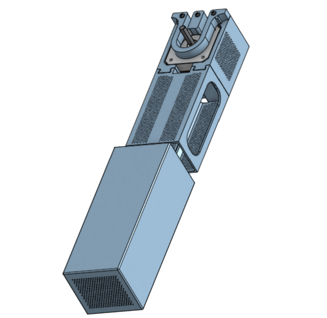
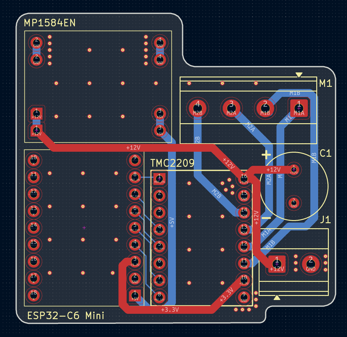
The main mechanical component is the mount, featuring two compartments. A thick-walled compartment which is load-bearing and contains the NEMA17, in addition to a thin-walled circuit compartment.
To connect the NEMA17 to the mount, there is a face plate, which also features guides for the beaded-chain to be routed through.
There's also a cosmetic lid which is friction-fit using two pins for alignment and security, hiding the internal circuit while being easy to remove.
The sprocket is parametrically designed based on the following formulas.
The box features hexagonal ventilation holes which balance structural integrity and FDM manufacturability with sufficient surface area for thermal convection to prevent overheating.
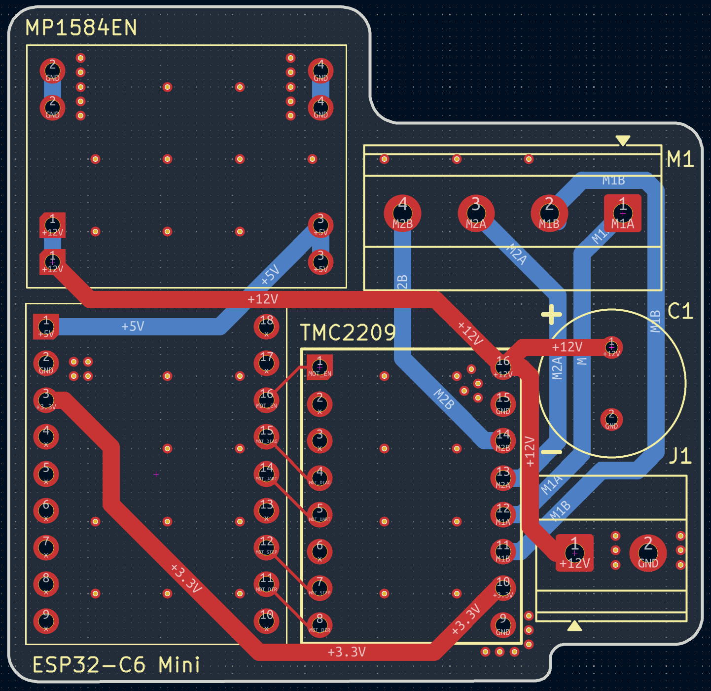
The electronics involved in this project are for controlling and powering the motor. The ESP32 is the brain, allowing programmed movement logic and eventually communication with Google Home and other smart home systems via Matter over WiFi. The TMC2209 acts as an interface between the ESP32 and the NEMA17, and via the StealthChop2 feature, it allows ultra-quiet motor movement. The MP1584EN is a simple buck converter to step down the 12V from the power supply to the 5V required for the ESP32.
I decided to use a custom PCB because I wanted to make multiple of the device, and eventually open-source it, so I decided inserting components into a PCB would be much easier than wiring spaghetti and frustrating breadboarding. It also gave me a chance to upskill KiCAD and learn about circuit schematics, rule checkers, and the PCB development and manufacturing process.
BOM
| Component | Source | Pack Size (Bought) | Qty Required | Pack Cost (AUD) | True Project Cost (AUD) |
|---|---|---|---|---|---|
| ESP32-C6 Mini Dev Board | Amazon AU | 1 | 1 | $25.01 | $25.01 |
| 12V 3A 36W Power Supply | Amazon AU | 1 | 1 | $21.99 | $21.99 |
| NEMA 17 Stepper Motor (34mm, 1.5A) | Amazon AU | 1 | 1 | $20.99 | $20.99 |
| TMC2209 V2.0 Stepper Driver | Amazon AU | 5 | 1 | $37.03 | $7.41 |
| MP1584EN 3A DC-DC Buck Converter | Amazon AU | 15 | 1 | $18.87 | $1.26 |
| Custom 2-Layer PCB | JLCPCB | 5 | 1 | $2.00 | $0.40 |
| M3 Button Head Screw Kit | Amazon AU | 300 | 8 | $10.99 | $0.29 |
| M3 Nylon Standoffs & Nuts Kit | Amazon AU | 320 | 4 | $12.99 | $0.16 |
| 3M VHB Double Sided Tape | Amazon AU | 33m | 10 cm | $12.99 | $0.04 |
| 2.1mmx5.5mm DC Power Jack (Panel Mount) | Amazon AU | 30 | 1 | $16.89 | $0.56 |
| 100µF 50V Electrolytic Capacitor (Polarized) | Jaycar Electronics | 1 | 1 | $1.00 | $1.00 |
| 60/40 Rosin Core Solder 0.71mm | Workshop | 15g | Variable | $0.00 | $0.00 |
| 24 AWG Solid Core Hookup Wire | Workshop | N/A | Variable | $0.00 | $0.00 |
| Totals | $180.75 | $79.11 |
I wanted to keep this deliberately simple and write it fully myself so I could understand how the stepper control loop works, rather than relying on agentic tools to write something complex that I wouldn't fully understand under the hood.
What it does:
What it deliberately doesn't do (and why):
Walkthrough
read_int(): Serial user input parser that checks for user commands and accepts valid inputs as commands (0: Stop, 1: Top, 2: Bottom).FastAccelStepper Engine: Asynchronously drives the STEP/DIR signal generation using ESP32 hardware timers, allowing smooth acceleration and deceleration ramps in the background.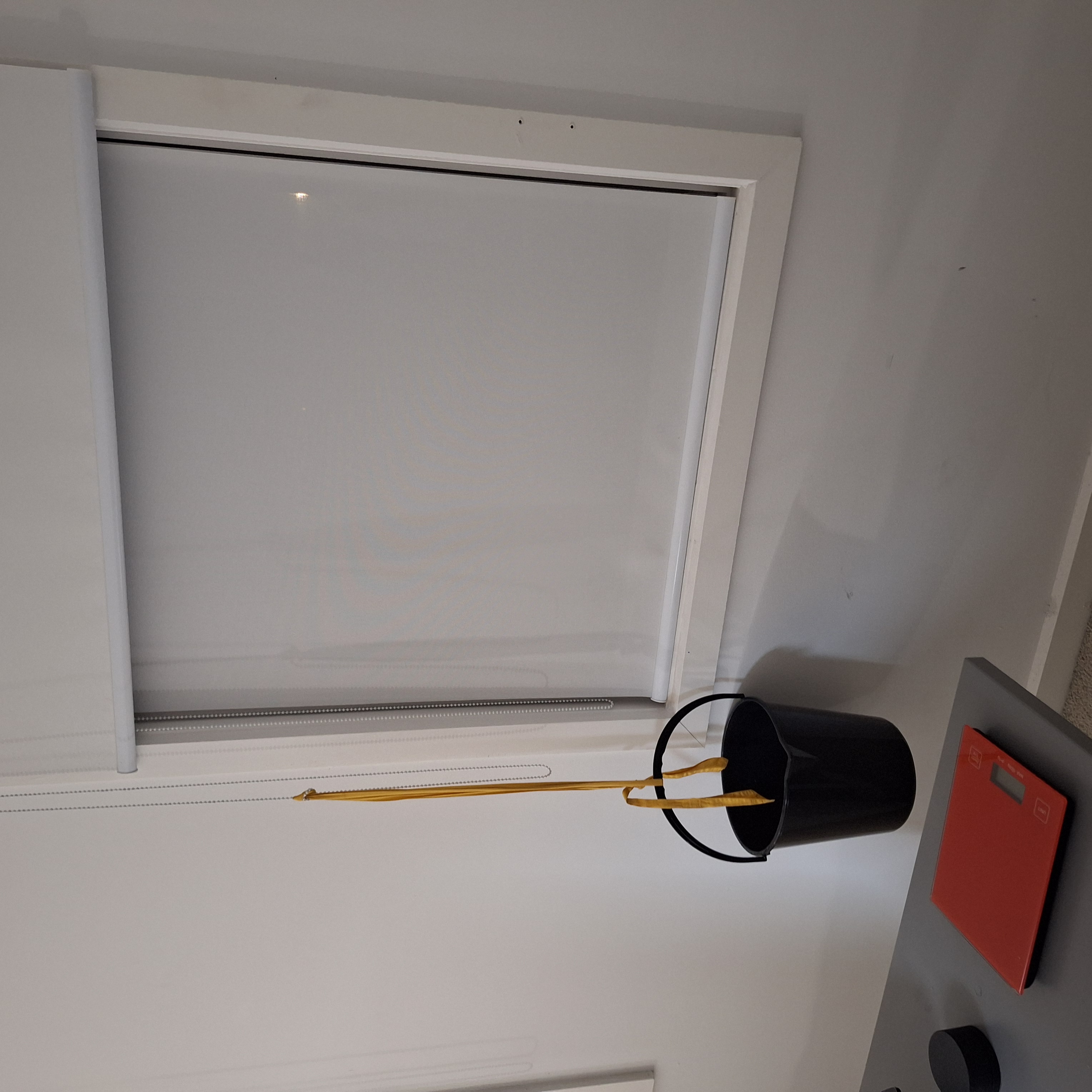
#include <Arduino.h>
#include <FastAccelStepper.h>

constexpr int PIN_EN = 14;
constexpr int PIN_SPREAD = 15;
constexpr int PIN_UART = 18;
constexpr int PIN_STEP = 20;
constexpr int PIN_DIR = 21;

constexpr int SPEED = 500;  // step per sec
constexpr int ACCEL = 1000; // step per sec^2

constexpr int TOP_POSITION = 0;       // steps
constexpr int BOTTOM_POSITION = 1000; // steps

enum user_input
{
  PAUSE,
  TOP,
  BOTTOM,
  OPTIONS_COUNT
};

user_input command = PAUSE;
| Test | Result |
|---|---|
| Bucket test - required pulling force | 1.8kg confirmed |
| Noise level (<40dB target) | Not yet tested |
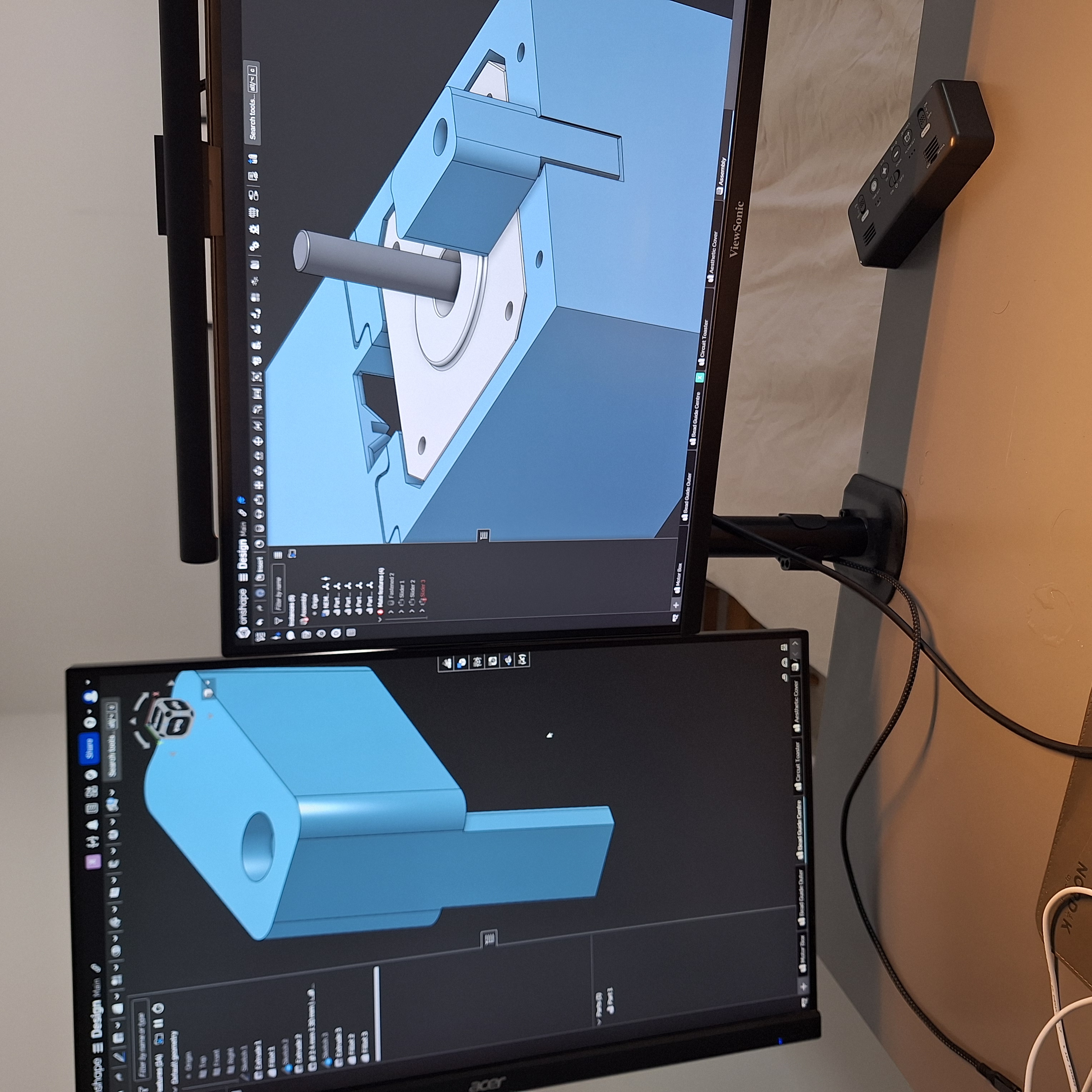
I learned a massive amount from this project. On the CAD side, I learned about using variables in my designs, rather than "magic numbers" for dimensions, so everything in my design is fully adjustable via the variables table. I also learned about a lot more Onshape's sketch tools (tangent, normal, and perpendicular constraints), as well as their 3D tools (Featurescripts like Grid Extrude for ventilation, alongside operations like revolve which I used for the sprocket).
I also learned KiCAD from scratch during this project, which was a great learning experience and upskilling opportunity into a new field. Historically I used graphical software like Canva or Illustrator for circuit diagrams, but learning how to write proper, verified schematics was really enjoyable, and seeing my own custom-designed PCB arrive was extremely rewarding. Contrary to what I used to assume about PCBs, it actually saved me time, as I used to have to spend weeks fiddling with breadboards because I didn't take the time to plan my circuit thoroughly. That, combined with the time saved from soldering (only took ~10min to solder the entire PCB!), allowed me to finalise all electronics in about a week.
/firmware/firmware/legacy/docs/research-log/hardware/pcb/hardware/cadThis project is licensed under the MIT License. See the LICENSE file for details.
Personal project, July 2026.
| Qty | Value | Footprint | References |
|---|---|---|---|
| 1 | 100µF | Capacitor_THT:C_Radial_D10.0mm_H20.0mm_P5.00mm | C1 |
| 1 | Barrel_Jack | TerminalBlock_Phoenix:TerminalBlock_Phoenix_MKDS-1,5-2-5.08_1x02_P5.08mm_Horizontal | J1 |
| 1 | Stepper_Motor_bipolar | TerminalBlock_Phoenix:TerminalBlock_Phoenix_MKDS-1,5-4-5.08_1x04_P5.08mm_Horizontal | M1 |
| 1 | ~ | auto-blinds:ESP32-C6-Super-Mini-Header | ESP32-C6-Super-Mini1 |
| 1 | ~ | auto-blinds:TMC2209-Module | TMC2209 |
| 1 | ~ | auto-blinds:MP1584EN-Module | MP1584EN1 |
It measures 48 × 46.6 mm and has 2 copper layers, 1.6 mm thick.
6 parts. The full list of its parts is on this page, with links to each part's symbol and footprint where PCBKit's library has them.
From the xavier-phillips/stepper-blinds-driver repository on GitHub, at the commit this page was made from: the board is hardware/pcb/kicad/kicad.kicad_pcb and its schematic hardware/pcb/kicad/kicad.kicad_sch. PCBKit opens the board in the browser, with nothing to install.
Its repository publishes it under the MIT licence: you may reuse it on that licence's terms (keep the author's notice, and for a copyleft licence share your changes alike).
byrantech/laptop
anyon_e, a highly integrated, high end, open source laptop. Attempt the impossible.


Jcparkyn/dpoint
Open-source digital stylus using camera tracking and inertial measurements

VoronDesign/Voron-Hardware
Cool Hardware designed by the Voron Design group

hoglet67/RGBtoHDMI
Bare-metal Raspberry Pi project that provides pixel-perfect sampling of Retro Computer RGB/YUV video and conversion to HDMI

hackclub/OnBoard
💡 Join 1,000 teenagers and make your first PCB with a $100 grant!

Luos-io/luos_engine
Open-source and real-time orchestrator for cyber-physical-systems, to easily design, test and deploy embedded applications and digital twins.
