
2 layers10.5 × 12 mm

A low-cost launch monitor that recovers a ball's launch vector from one high-speed monochrome camera and one 24 GHz CW Doppler radar — the RF front-end, the acquisition firmware, the synchronized recorder, and the…
Radar board is an open-source printed circuit board by wzwqoo, from the wzwqoo/single_camera_single_radar_rx_launch_monitor repository on GitHub. It is a 4-layer board of 58 × 56.1 mm with 82 parts on 45 nets, routed with 685 tracks and 71 vias.
It is built around the TLV9001IDCK and TPS74801DRCR. Its parts include 39 capacitors, 33 resistors, 4 connectors and 3 ICs.


A low-cost launch monitor that recovers a ball's launch vector from one high-speed monochrome camera and one 24 GHz CW Doppler radar — the RF front-end, the acquisition firmware, the synchronized recorder, and the processing that turns both streams into a single answer.
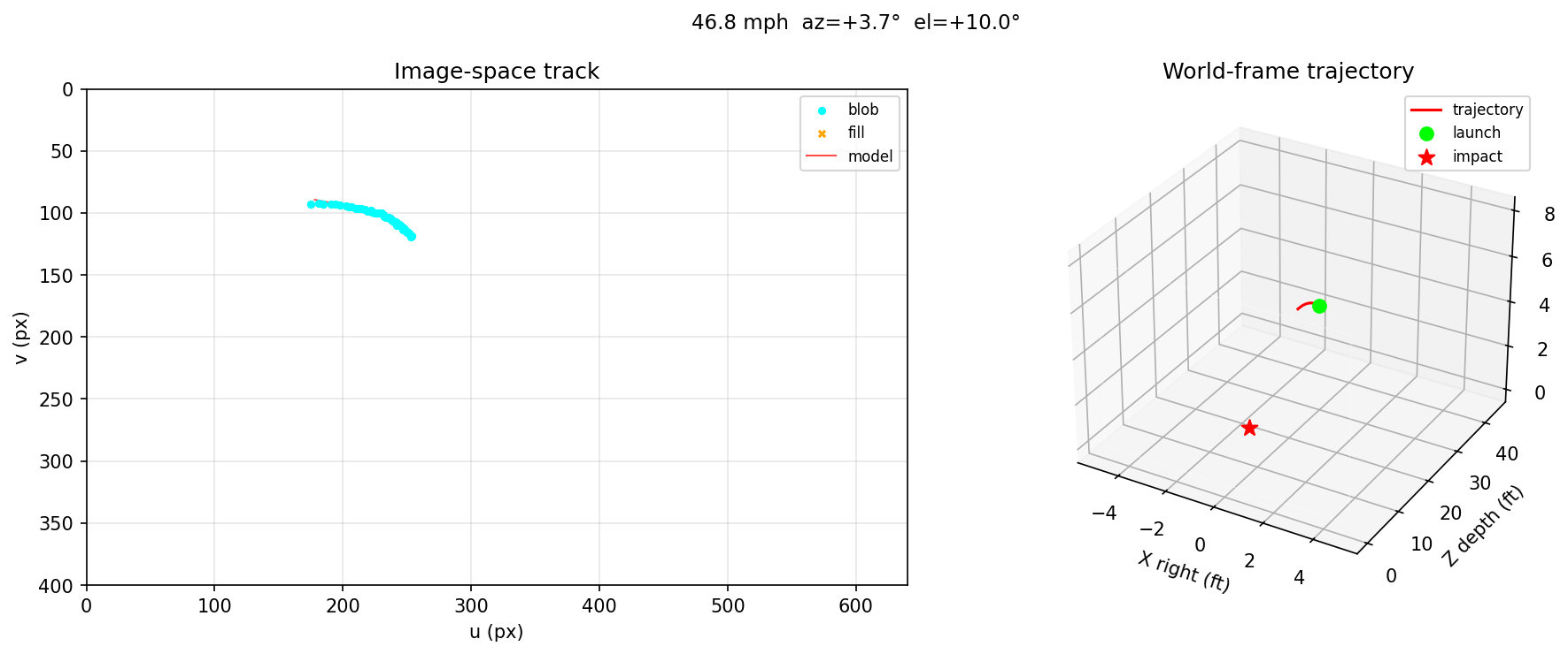
Left: per-frame ball detections tracked through the image. Right: the same flight reconstructed in the world frame. Header: the resulting launch state — speed, azimuth, elevation.
Each sensor alone measures half the problem, and each is blind exactly where the other is strong:
| measures well | cannot measure | |
|---|---|---|
| Radar (CW Doppler) | speed along the line of sight, to ≈0.5 mph | launch direction — one channel gives one scalar |
| Camera (mono, 210 fps) | launch azimuth and elevation, over-determined by ~10–15 frames | absolute depth — a single view is nearly blind along its own optical axis |
So the system is built around a deliberate split of labour: radar supplies the speed magnitude, the camera supplies the direction. The camera is never asked for absolute scale, and the radar is never asked for geometry.
flowchart LR
    A["OV9281 camera<br/>640×400 @ 210 fps"] --> C["blob / contour detection<br/>→ Kalman track"]
    C --> D["bundle adjustment<br/>vs. known wall plane"]
    D --> F["launch azimuth<br/>+ elevation"]
    B["K-LC7 24 GHz radar<br/>→ STM32 → USB"] --> E["Doppler STFT<br/>→ peak speed"]
    E --> G["line-of-sight<br/>speed |v|"]
    F --> H["fused launch vector<br/>v / cos γ, az, el"]
    G --> H
A single tool records both sensors together, so every radar clip has a matching optical trajectory and vice versa.
Both sensors are commodity parts; the only custom electronics is the radar's IF carrier board. Full details in hardware/ and firmware/.
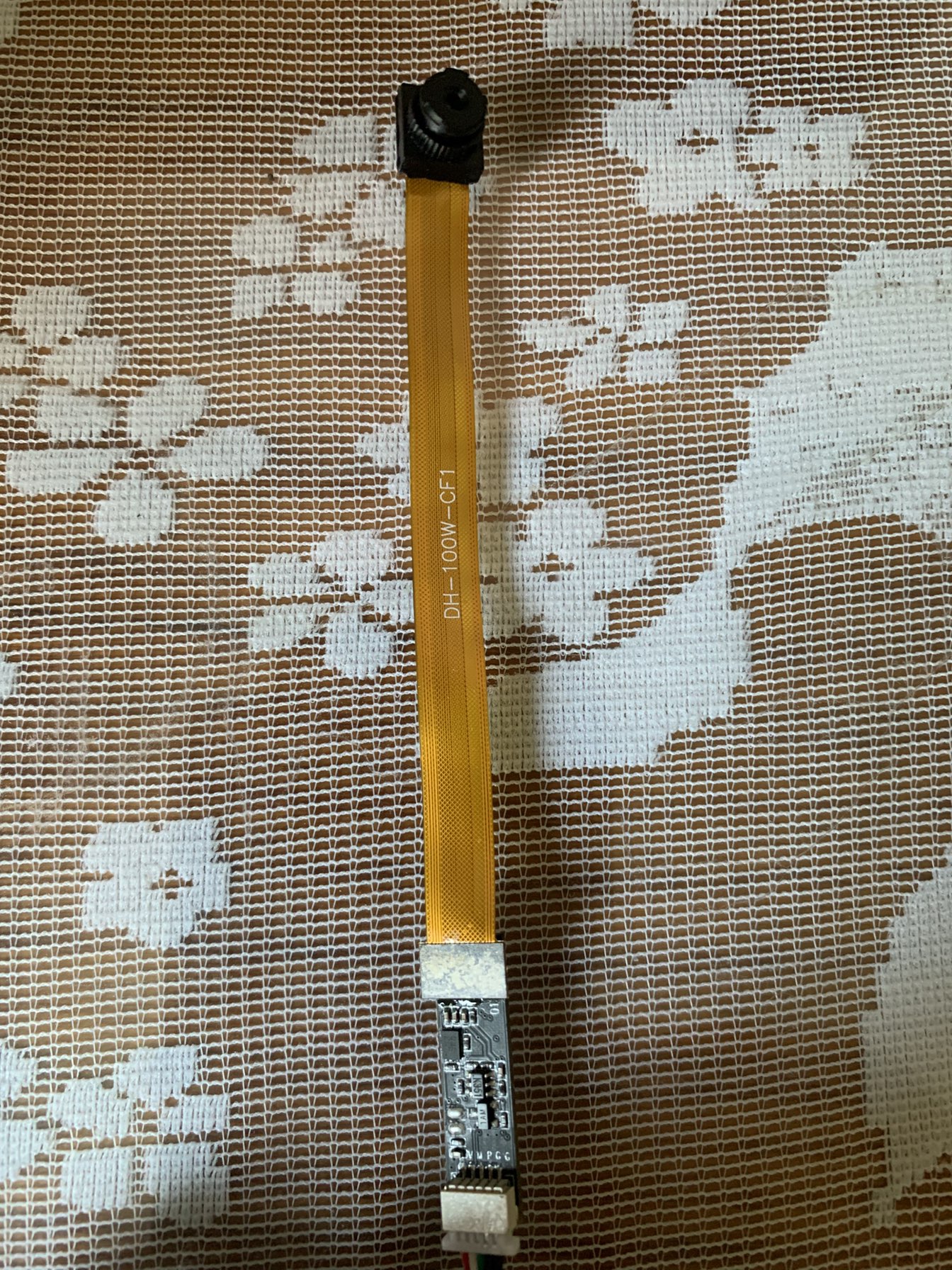
The camera as fielded: the OV9281 sensor and lens on a flex ribbon, with the USB interface board at the far end.
| Sensor | OmniVision OV9281 — 1 MP monochrome CMOS, global shutter, ≈$15 module |
| Mode | 640×400 MONO8 at 210 fps, hardware MJPEG over USB 2.0 |
| Optics | wide-angle, HFOV ≈ 75° ⇒ f ≈ 417 px |
| Geometry | camera 53 ft from a wall plane; a known wall circle spans ≈27 px, confirming the focal length |
Global shutter is a correctness requirement rather than a convenience: apparent ball diameter is the depth measurement, and rolling-shutter skew would corrupt the very quantity being calibrated. Monochrome readout drops the Bayer mosaic, which matters when the ball is only 3–25 px across.
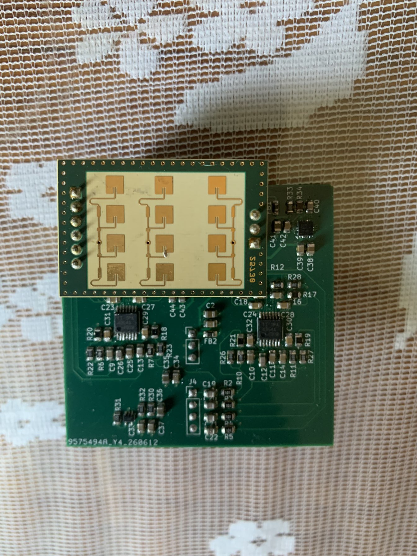
The K-LC7 transceiver module (top, patch-array antenna side) mounted on the custom IF carrier board carrying the two-stage amplifier chain.
| Module | RFbeam K-LC7, 24.0–24.25 GHz ISM, CW Doppler transceiver with integrated VCO |
| Receive | two coherent I/Q pairs; I/Q phase 80–100°, amplitude imbalance ±3 dB |
| Sensitivity | −96 dBm (1 kHz BW, 6 dB S/N) |
| IF board | custom carrier: two ×32 stages = 60 dB, high-pass corner ≈3.4 kHz |
| MCU | STM32F446 — dual ADC + DMA at 24 kSPS/channel, FreeRTOS, USB CDC |
| Antenna study | 24.125 GHz stepped horn, 65×50 mm aperture, modelled in MATLAB |
The module's 100 kHz VCO modulation bandwidth is what forces the CW architecture: FMCW at sports-ball speeds would need an unambiguous velocity far above the ≈28 mph this bandwidth allows. CW buys speed and spin at the cost of all range information.
Each folder has its own README with the details.
| Path | Contents |
|---|---|
| hardware/ | K-LC7 IF carrier board (KiCad project + fab/ Gerbers), 24 GHz horn-antenna study, module datasheet |
| firmware/ | STM32F446 acquisition firmware — timer-paced dual-ADC DMA, on-board Doppler trigger, USB CDC raw streaming |
| capture/ | Synchronized camera + radar recording, camera calibration, clip trimming |
| tracking/ | Camera pipeline: detection → mono track → 3-D trajectory fit → launch angles |
| radar/ | Doppler speed and micro-Doppler spin-rate extraction from recorded I/Q |
| data/radar_captures/ | Eight raw throw captures, with the speed measured from each |
| docs/ | Figures used by these READMEs |
pip install -r requirements.txt

# 1. Calibrate the camera (once, per lens)
python capture/1_calibrate_camera.py

# 2. Record camera + radar together; space bar starts/pauses both streams
python capture/3_record_combined.py /dev/ttyACM0

# 3. Trim the radar clips to the frames you kept
python capture/6_trim_to_frames.py --frames camera_frames --radar radar_data

# 4. Radar → speed magnitude
python radar/speed_test.py radar_data/rx2_YYYYMMDD_HHMMSS.npz

# 5. Camera → launch direction (and the full reconstruction)
python tracking/explore.py camera_frames --out throw01
Firmware builds with STM32CubeIDE or the included CMake preset; the horn model needs MATLAB with the Antenna Toolbox.
This is a research build, and the honest scope is narrower than "launch monitor" suggests:
explore.py post-processes a complete clip; the question
it answers is "given every frame, how trustworthy is the answer", not "how fast can
this converge".| Qty | Value | Footprint | References |
|---|---|---|---|
| 14 | 100nF | Capacitor_SMD:C_0805_2012Metric | C1, C10, C11, C14, C16, C18, C25, C33, C34, C37, C39, C42, C44, C45 |
| 11 | 10nF | Capacitor_SMD:C_0805_2012Metric | C9, C12, C13, C15, C17, C19, C20, C21, C22, C26, C40 |
| 9 | 31K2 | Resistor_SMD:R_0805_2012Metric | R14, R15, R16, R17, R18, R19, R20, R21, R34 |
| 8 | 1K | Resistor_SMD:R_0805_2012Metric | R22, R23, R24, R25, R26, R27, R28, R29 |
| 8 | 330pF | Capacitor_SMD:C_0805_2012Metric | C23, C24, C27, C28, C29, C30, C31, C32 |
| 4 | 100 | Resistor_SMD:R_0805_2012Metric | R2, R3, R4, R5 |
| 4 | 100K | Resistor_SMD:R_0805_2012Metric | R10, R11, R12, R13 |
| 4 | 22uF | Capacitor_SMD:C_0805_2012Metric | C35, C36, C41, C43 |
| 4 | 4K7 | Resistor_SMD:R_0805_2012Metric | R6, R7, R8, R9 |
| 3 | 10K | Resistor_SMD:R_0805_2012Metric | R30, R32, R33 |
| 2 | 10uF | Capacitor_SMD:C_0805_2012Metric | C2, C38 |
| 2 | 600Ω@100MHz | Inductor_SMD:L_0805_2012Metric | FB1, FB2 |
| 2 | OPA4354AIPWR | Package_SO:TSSOP-14-1EP_4.4x5mm_P0.65mm | U1, U2 |
| 1 | 22 | Resistor_SMD:R_0805_2012Metric | R31 |
| 1 | Conn_01x03_Pin | Connector_PinHeader_2.54mm:PinHeader_1x03_P2.54mm_Vertical | J5 |
| 1 | Conn_01x03_Socket | Connector_PinSocket_2.54mm:PinSocket_1x03_P2.54mm_Vertical | J1 |
| 1 | Conn_01x04_Pin | Connector_PinHeader_2.54mm:PinHeader_1x04_P2.54mm_Vertical | J4 |
| 1 | Conn_01x06_Socket | Connector_PinSocket_2.54mm:PinSocket_1x06_P2.54mm_Vertical | J2 |
| 1 | TLV9001IDCK | Package_TO_SOT_SMD:SOT-353_SC-70-5 | U3 |
| 1 | TPS74801DRCR | Package_SON:VSON-10-1EP_3x3mm_P0.5mm_EP1.65x2.4mm | TPS74801DRCR1 |

wzwqoo/Echometer
KiCad 10 project (v4.kicadpro, schematic + 4-layer PCB), fabrication outputs in fab/, BOM in v4.csv, and the parametric acoustic-horn generator ultrasonichornfreecad.py.

jayis1/hacker-devices
Full-cycle hardware designs for security research devices — each device is a subfolder with its own README, schematics, PCB layout, and software stack

ZigEmbeddedGroup/sycl-badge
The badge for the SYCL conference! https://zigembeddedgroup.github.io/sycl-badge/


Misaka0x2730/YukaLink
Dual targets USB+ETH ARM JTAG/SWD debugger (BlackMagic port) based on RP2350. JTAG and SWD interfaces are implemented on PIO.


It measures 58 × 56.1 mm and has 4 copper layers, 1.61 mm thick.
82 parts, built around the TLV9001IDCK and TPS74801DRCR. The full list of its parts is on this page, with links to each part's symbol and footprint where PCBKit's library has them.
From the wzwqoo/single_camera_single_radar_rx_launch_monitor repository on GitHub, at the commit this page was made from: the board is hardware/radar_board/hardware.kicad_pcb and its schematic hardware/radar_board/baseband.kicad_sch. PCBKit opens the board in the browser, with nothing to install.
Its repository states no licence, so its author keeps all rights: ask wzwqoo before reusing the design.