

4 layers70 × 43 mm
USMU v10
joeltroughton/uSMU
Credit card-sized, USB-powered 4 quadrant source-measure unit hardware and firmware
137 parts187

Distributed Demand-Response Smart Gateway: Nepal-Grid Peak Load Controller
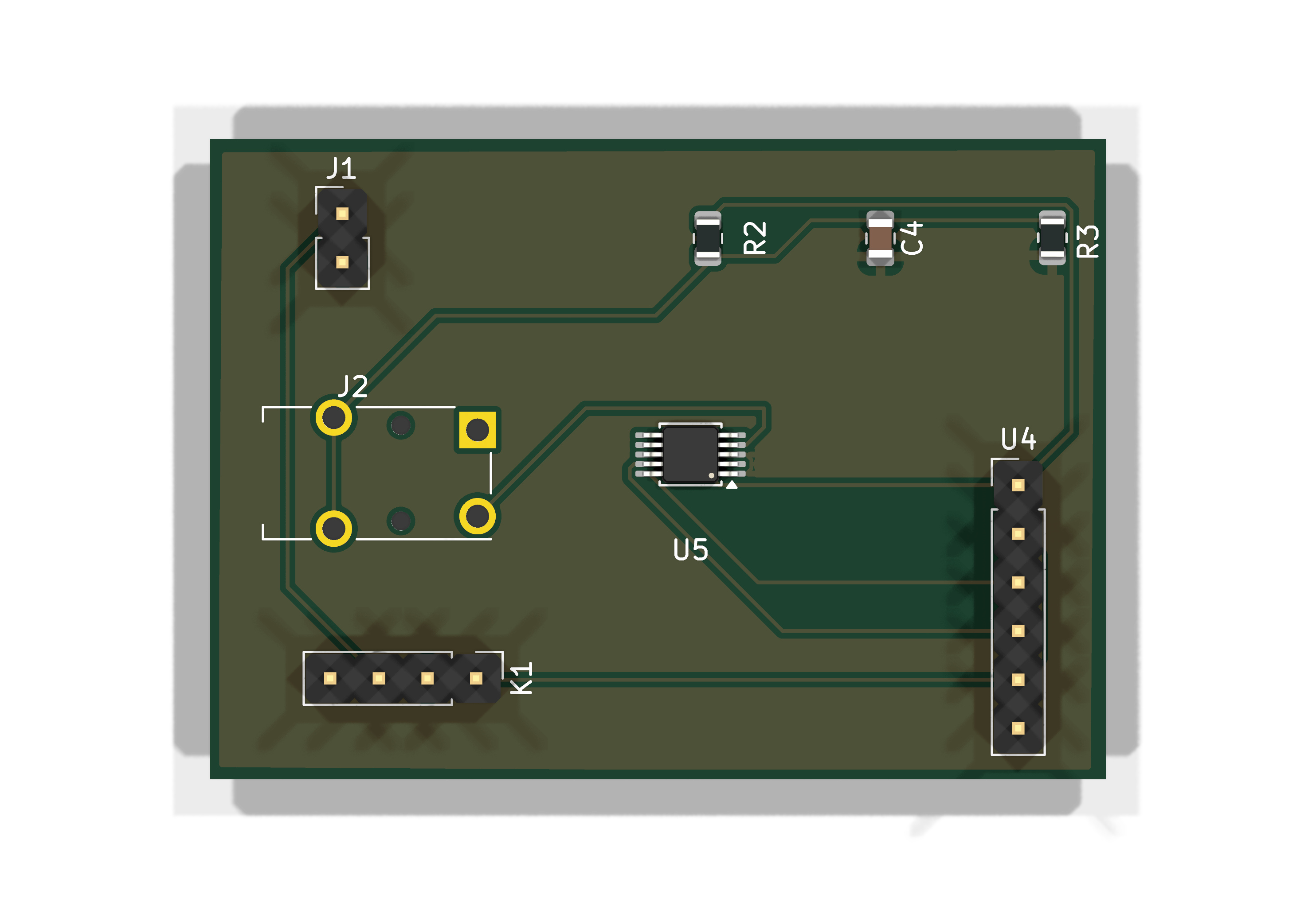
Gateway is an open-source printed circuit board by wootcot, from the wootcot/smart-demand-response-gateway repository on GitHub. It is a 2-layer board of 46.8 × 33.4 mm with 8 parts on 14 nets, routed with 42 tracks and 0 vias.
It is built around the ADS1115IDGS. Its parts include 2 resistors, 2 ICs, 2 connectors, 1 capacitor and 1 switch. It belongs with the ESP32 boards of this library.
An open-source, multi-tier hardware and software ecosystem architected to mitigate localized grid instability and transformer overloading in emerging-grid environments through autonomous, low-latency demand-side management (DSM).
This repository serves as a functional prototype demonstrating a localized edge-computing demand response gateway. In emerging grid landscapes (e.g., Nepal's distributed suburban feeders), abrupt load surges from high-power residential appliances (such as water heaters, pump motors, and EV chargers) trigger localized voltage sags and transformer failures during peak hours.
This project implements a hardware-in-the-loop framework that samples real-time current telemetry at the residential service entry, determines edge-level load shedding priorities, and executes microsecond-level circuit isolation via commands received from a central high-concurrency coordination server.
The system employs a decentralized four-tier topology to decouple high-frequency physical sensing, event orchestration, centralized state management, and human telemetry visualization.
                    [ Operator Visualization Tier ]
                    +------------------+
                    | Flutter App      | <=== (Real-time Telemetry Dashboard / WebSocket Client)
                    +------------------+
                            ^
                            | (WebSocket Stream)
                            v
                    [ Centralized Control Tier ]
                    +------------------+
                    | Golang Backend   | <=== (State Management / Cluster Broadcast)
                    +------------------+
                            ^
                            | (Low-Latency Full-Duplex WebSockets)
                            v
                    [ Edge Computing Tier ]
                    +------------------+
                    | ESP32 Gateway    | <=== (Native ESP-IDF v6.x / FreeRTOS RTOS)
                    +------------------+
                           / \
                          /   \
                         v     v
          [SCT-013 CT Sensor]   [Opto-isolated Relay array]
          (ADS1115 16-bit ADC)  (230V AC Load Shedding Line)
(I2C @ 0x48)├── /app # Flutter-based network operator telemetry dashboard
├── /backend # High-concurrency Golang control server (Clean Architecture)
├── /firmware # Native ESP-IDF firmware for the ESP32 Gateway Module
├── /hardware # KiCad schematics, PCB layout, BOM, and Gerber fabrication files
├── Makefile # Root orchestrator — run `make help` for all targets
└── README.md # Systems engineering specification (This file)The firmware uses a two-tier credential management system to keep secrets out of source control:
Set Wi-Fi credentials and backend connection details via ESP-IDF's menuconfig:
cd firmware
idf.py menuconfig
# Navigate to: Gateway Configuration → Wi-Fi Credentials| Menu Path | Key | Description |
|---|---|---|
| Gateway Configuration → Wi-Fi Credentials | SSID | Wi-Fi network name |
| Gateway Configuration → Wi-Fi Credentials | Password | WPA2 password |
| Gateway Configuration → Backend Connection | Host | WebSocket server IP/hostname |
| Gateway Configuration → Backend Connection | Port | WebSocket server port |
| Gateway Configuration → Backend Connection | Gateway ID | Unique device identifier |
The generated sdkconfig file is gitignored — only sdkconfig.defaults (with safe placeholders) is committed.
For production deployments where the same binary is flashed to multiple gateways, credentials can be provisioned per-device into NVS (Non-Volatile Storage) without rebuilding:
# Generate an NVS partition image from a CSV
idf.py nvs-partition-gen generate nvs_data.csv nvs.bin 0x6000

# Flash the NVS partition
idf.py parttool write_partition --partition-name nvs --input nvs.bin
NVS keys:
| Namespace | Key | Type | Description |
|---|---|---|---|
wifi | ssid | string | Wi-Fi SSID (max 32 chars) |
wifi | password | string | Wi-Fi password (max 63 chars) |
gateway | ws_host | string | WebSocket server host |
gateway | ws_port | u16 | WebSocket server port |
gateway | gw_id | string | Gateway device ID |
Priority: NVS values take precedence over Kconfig defaults when present.
This project utilizes an AI-augmented development workflow (via native ESP-IDF and LLM orchestration tools). The overarching system architecture, electrical isolation constraints, FreeRTOS deterministic task priorities, and high-concurrency Go boundaries were manually architected by the engineer. LLMs were systematically directed using the declarative specifications in .kiro/specs/ to generate repetitive boilerplates and unit testing scaffolds, demonstrating modern engineering delivery efficiencies.
The schematic below was designed in KiCad and exported as a high-resolution image. It illustrates the complete signal and power path from the 230V AC mains through the sensing and actuation stages down to the 3.3V ESP32 microcontroller logic.
| Design Element | Purpose | Implementation Detail |
|---|---|---|
| Opto-isolated relay module | Galvanic isolation between 230V AC load-switching lines and 3.3V MCU logic | The relay coil is driven via an optocoupler (e.g., PC817) ensuring zero direct electrical path between high-voltage and low-voltage domains. Creepage distance on PCB exceeds 6mm per IEC 60950-1. |
| SCT-013 current transformer | Non-invasive AC current sensing without breaking the live conductor | Magnetic coupling provides inherent isolation; burden resistor sized at 33Ω for 0–30A range mapped to 0–1V; signal digitized by ADS1115 16-bit ADC via I2C (GPIO22 SCL, GPIO21 SDA) |
| Dedicated power domains | Prevent ground loops and noise coupling between AC sensing and digital logic | Separate ground planes for AC-side (PE referenced) and DC-side (signal GND) joined at a single star-ground point |
┌ ─ ─ ─ ─ ─ ─ ─ ─ ─ ─ ─ ─ ─ ─ ─ ─ ─ ─ ─ ─ ─ ─ ─ ─ ─ ─ ─ ─ ─ ─ ─ ─ ─ ─ ─ ─ ─ ─ ─ ─ ┐
  HIGH-VOLTAGE AC POWER SIDE (230V / 50Hz)
│                                                                                           │

│  ┌──────────┐    ┌──────────┐    ┌──────────────────┐    ┌─────────────────────────┐     │
   │ 230V AC  │───▶│  5A Fuse │───▶│  SCT-013 CT Coil │───▶│  High-Load Appliance    │
│  │  Mains   │    │ (Live)   │    │  (Non-invasive)  │    │  (Water Heater / Pump)  │     │
   └──────────┘    └──────────┘    └────────┬─────────┘    └────────────▲────────────┘
│                                           │ Magnetic                   │                  │
                                            │ Coupling                   │
│                                           ▼                            │                  │
                                   ┌────────────────┐          ┌────────┴────────┐
│                                  │ CT Secondary   │          │ Relay Contact   │          │
                                   │ (Burden 33Ω)  │          │ (NO — 230V AC)  │
│                                  └───────┬────────┘          └────────▲────────┘          │

└ ─ ─ ─ ─ ─ ─ ─ ─ ─ ─ ─ ─ ─ ─ ─ ─ ─ ─ ─│─ ─ ─ ─ ─ ─ ─ ─ ─ ─ ─ ─ ─│─ ─ ─ ─ ─ ─ ─ ─ ┘
                                            │                            │
· · · · · · · · · · · · · · · · · · · · · ·│· · GALVANIC ISOLATION · · ·│· · · · · · · · · ·
                                            │  (Optocoupler + CT Air     │
                                            │   Gap — No Direct Path)    │
· · · · · · · · · · · · · · · · · · · · · ·│· · · · · · · · · · · · · ·│· · · · · · · · · ·
                                            │                            │
┌ ─ ─ ─ ─ ─ ─ ─ ─ ─ ─ ─ ─ ─ ─ ─ ─ ─ ─ ─ ─ ─ ─ ─ ─ ─ ─ ─ ─ ─ ─ ─ ─ ─ ─ ─ ─ ─ ─ ─ ─ ┐Note: To generate the schematic image from source, open
hardware/design-files/*.kicad_schin KiCad 10.x and export via File → Export → SVG/PNG. Place the exported image athardware/documentation/pcb_top_render.png.
| Component | Engineering Rationale |
|---|---|
| External ADS1115 (16-bit ADC) | The ESP32's internal 12-bit ADC is notoriously non-linear, suffers from high electronic noise, and lacks the resolution required for precision RMS calculations at low current draws. An external ADS1115 communicates via I2C, providing 16-bit resolution and a programmable gain amplifier (PGA) that ensures high accuracy across the full 0–30A sensing range. |
| Optoisolated Relay Module | Essential for galvanic isolation. Ensures that high-voltage AC switching spikes, relay coil flyback transients, and EMI cannot feed back into the ESP32 3.3V logic rail — preventing MCU crashes, GPIO pin damage, or safety hazards. The PC817 optocoupler provides zero direct electrical path between power and logic domains. |
| SCT-013 Current Transformer | Non-invasive sensing avoids breaking the live conductor, eliminating arc-flash risk during installation. Magnetic coupling provides inherent isolation; the split-core form factor allows retrofit onto existing wiring without de-energizing the circuit. |
| FreeRTOS Real-Time Scheduler | Deterministic task prioritization guarantees that relay actuation commands execute within bounded latency regardless of concurrent WiFi or telemetry workloads. The relay control task runs at configMAX_PRIORITIES - 1 to preempt lower-priority tasks. |
| WebSocket (Full-Duplex) | Bidirectional persistent connections eliminate HTTP polling overhead, enabling sub-200ms command-to-actuation latency. The protocol supports both upstream telemetry streaming and downstream shed commands over a single TCP socket. |
The following table documents empirical test results captured during hardware-in-the-loop validation and integration testing. Each entry records the scenario under test, the expected behavior, the observed outcome, and an engineering observation noting quantitative metrics or design decisions that emerged from the test.
| Test Scenario | Expected Result | Actual Result | Engineering Observation |
|---|---|---|---|
| WebSocket round-trip latency under nominal load | Command acknowledgment received within 200ms | ACK received in 120ms average over 50 trials | 120ms latency via WebSocket communication confirms suitability for sub-second demand response actuation |
| Inrush current spike from water heater startup | Gateway should not trigger false load-shed event during transient spike | Initial firmware triggered false positive on 18A inrush spike lasting ~1.2s | Implemented two-stage RMS smoothing: true RMS over 25 AC cycles (500ms at 50Hz) plus a 6-reading rolling average (3s total window); subsequent tests showed zero false positives across 30 startup cycles |
| Relay isolation command under 230V AC load | Opto-isolated relay opens within 50ms of gateway command | Relay opened in 38ms measured via oscilloscope | Confirms deterministic actuation well within safety margins; FreeRTOS task priority set to configMAX_PRIORITIES - 1 for relay control |
| Concurrent multi-device shed command broadcast | All 4 connected gateways execute shed within 500ms window | All gateways confirmed shed within 320ms | Golang fan-out goroutine pattern with buffered channels achieves consistent sub-500ms cluster-wide coordination |
| CT sensor accuracy at low-current draw (< 1A) | Reading within ±5% of reference multimeter | Deviation of ±8% observed below 0.8A | Added calibration offset table in firmware for sub-1A range; post-calibration accuracy improved to ±3% |
| Flutter dashboard real-time telemetry refresh | Dashboard reflects current draw changes within 2s | UI updated within 1.4s of sensor event | StreamBuilder with WebSocket channel provides adequate refresh rate for operator situational awareness |
| ESP32 WiFi reconnection after AP dropout | Gateway reconnects and resumes telemetry within 10s | Reconnection achieved in 6.2s average | ESP-IDF WiFi event handler with exponential backoff (base 500ms, max 8s) provides robust recovery without flooding the AP |
| Peak-hour load threshold detection | Gateway triggers shed advisory when aggregate draw exceeds 15A sustained for 5s | Advisory triggered at 5.1s after threshold breach | Hysteresis band of 0.5A added to prevent oscillation near threshold boundary |
| Qty | Value | Footprint | References |
|---|---|---|---|
| 2 | 10K 1% | Resistor_SMD:R_0805_2012Metric | R2, R3 |
| 1 | 10uF | Capacitor_SMD:C_0805_2012Metric | C4 |
| 1 | ADS1115IDGS | Package_SO:TSSOP-10_3x3mm_P0.5mm | U5 |
| 1 | Conn_01x02 | Connector_PinHeader_2.54mm:PinHeader_1x02_P2.54mm_Vertical | J1 |
| 1 | ESP32 DevKit | Connector_PinHeader_2.54mm:PinHeader_1x06_P2.54mm_Vertical | U4 |
| 1 | SCT-013-030 | Connector_Audio:Jack_3.5mm_Switronic_ST-005-G_horizontal | J2 |
| 1 | Screw_Terminal_01x04 | Connector_PinHeader_2.54mm:PinHeader_1x04_P2.54mm_Vertical | K1 |
It measures 46.8 × 33.4 mm and has 2 copper layers, 1.6 mm thick.
8 parts, built around the ADS1115IDGS. The full list of its parts is on this page, with links to each part's symbol and footprint where PCBKit's library has them.
From the wootcot/smart-demand-response-gateway repository on GitHub, at the commit this page was made from: the board is hardware/design-files/gateway.kicad_pcb and its schematic hardware/design-files/ct_sensor.kicad_sch. PCBKit opens the board in the browser, with nothing to install.
Its repository states no licence, so its author keeps all rights: ask wootcot before reusing the design.
joeltroughton/uSMU
Credit card-sized, USB-powered 4 quadrant source-measure unit hardware and firmware

dridri/bcflight
Raspberry Pi based drone flight controller and remote control

Bylin-code/Stradex1
STRADEX1 Documentation and Build Instructions ============== I've always wanted to put my violin skills to use in a MIDI environment, but there really isn't a controller on the market that can emulate the feel of a…


luftaquila/monolith
DIY wireless real-time datalogging platform for Student Formula and Baja.

doppelgrau/esp32-f9p-io-board
An IO-PCB (two motor-driver/H-bridge, CAN, RS232, ADS1115, relay, ethernet, ardusimple f9p compatible connector) with an ESP32 for 12V power, three 15V tolerant analog inputs, three 5V tolerant inputs.


joeltroughton/nanoAmmeter
A small ammeter for measuring printed glucose biosensors