
4 layers70 × 43 mm
USMU v10
joeltroughton/uSMU
Credit card-sized, USB-powered 4 quadrant source-measure unit hardware and firmware
137 parts187
 Bylin-code/Stradex1101
STRADEX1 Documentation and Build Instructions ============== I've always wanted to put my violin skills to use in a MIDI environment, but there really isn't a controller on the market that can emulate the feel of a…
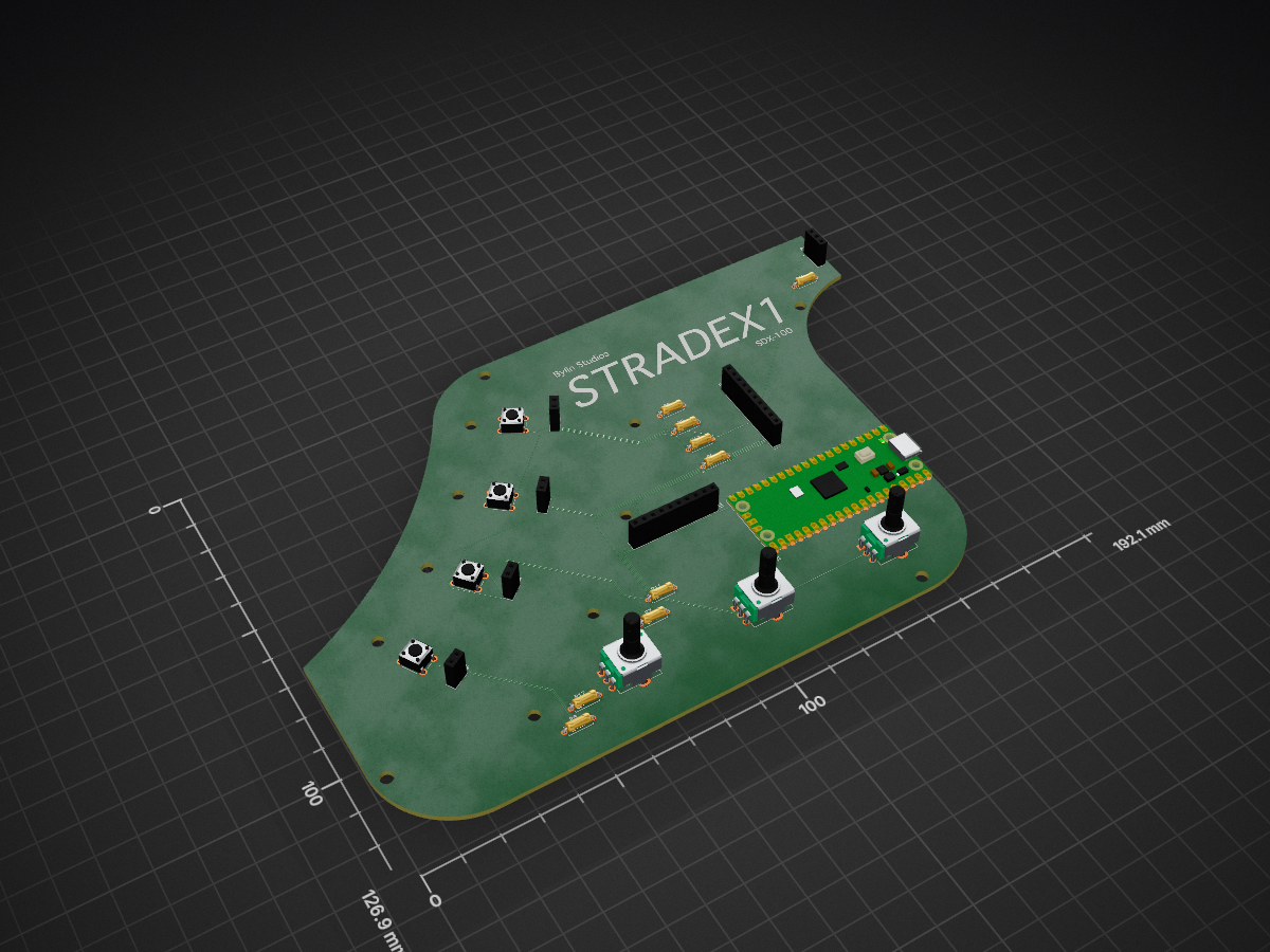
Stradex1 is an open-source printed circuit board by Bylin-code, from the Bylin-code/Stradex1 repository on GitHub. It is a 4-layer board of 192.1 × 126.9 mm with 24 parts on 42 nets, routed with 393 tracks and 0 vias.
It is built around the ADS1115IDGS. Its parts include 13 resistors, 4 switches and 2 ICs. It belongs with the RP2040 boards of this library.
I've always wanted to put my violin skills to use in a MIDI environment, but there really isn't a controller on the market that can emulate the feel of a violin to the extent that Stradex does.
Stradex features a SoftPot linear resistor to emulate the violin's fingerboard, four custom force-sensitive keys to emulate the strings, and three potentiometers for range & modulation control. This setup allows Stradex to generate pitch bends, vibrato, dynamic expression, and incredible range, all while remaining intuitive for the average string player.
This project took me a good while. Sure, there was a lot of time spent fiddling with faulty ADS1115 chips and iterating on key designs, but most of the headscratching was in the embedded firmware, namely, the MIDI signal interface. Many digital signal filtering and processing techniques had to be employed, including buffering, low-pass filtering, digital hysterisis, and numerous serial optimizations to ensure the controller intellegently decided when to send MIDI signals and when to ignore them.
BOM: 1x Raspberry Pi Pico 2 1x 8.5' SoftPot 2x ADS1115 breakout boards 3x 10k Potentiometers 4x 10k FSR 4x Soft tactile pushbuttons 10x Resistors (10k) 8x M3 18mm machine screws 4x M3 40mm machine screws 12x M3 flanged nuts
Instructions to make it:
Check out my website for more projects + contact me.
| Qty | Value | Footprint | References |
|---|---|---|---|
| 9 | 10k | Resistor_THT:R_Axial_DIN0207_L6.3mm_D2.5mm_P7.62mm_Horizontal | R5, R6, R7, R8, R9, R10, R11, R12, R17 |
| 4 | FSR | Connector_PinSocket_2.54mm:PinSocket_1x02_P2.54mm_Vertical | R1, R2, R3, R4 |
| 4 | SW_Push | Button_Switch_THT:SW_PUSH_6mm | SW1, SW2, SW3, SW4 |
| 3 | R_Pot | Potentiometer_THT:Potentiometer_Alpha_RD901F-40-00D_Single_Vertical | RV2, RV3, RV4 |
| 2 | ADS1115IDGS | Connector_PinSocket_2.54mm:PinSocket_1x10_P2.54mm_Vertical | U1, U2 |
| 1 | RaspberryPi_Pico | Module:RaspberryPi_Pico_Common_Unspecified | A1 |
| 1 | SoftPot | Connector_PinSocket_2.54mm:PinSocket_1x03_P2.54mm_Vertical | RV1 |
It measures 192.1 × 126.9 mm and has 4 copper layers, 1.6 mm thick.
24 parts, built around the ADS1115IDGS. The full list of its parts is on this page, with links to each part's symbol and footprint where PCBKit's library has them.
From the Bylin-code/Stradex1 repository on GitHub, at the commit this page was made from: the board is SDX_gerbers/Stradex1.kicad_pcb and its schematic SDX_gerbers/Stradex1.kicad_sch. PCBKit opens the board in the browser, with nothing to install.
Its repository states no licence, so its author keeps all rights: ask Bylin-code before reusing the design.
joeltroughton/uSMU
Credit card-sized, USB-powered 4 quadrant source-measure unit hardware and firmware

dridri/bcflight
Raspberry Pi based drone flight controller and remote control


luftaquila/monolith
DIY wireless real-time datalogging platform for Student Formula and Baja.

doppelgrau/esp32-f9p-io-board
An IO-PCB (two motor-driver/H-bridge, CAN, RS232, ADS1115, relay, ethernet, ardusimple f9p compatible connector) with an ESP32 for 12V power, three 15V tolerant analog inputs, three 5V tolerant inputs.


joeltroughton/nanoAmmeter
A small ammeter for measuring printed glucose biosensors
