2 layers15.2 × 20.3 mm

 willpuckett/tmtua
A drop-in connector for your quiet storm
Tmtua is an open-source printed circuit board by willpuckett, from the willpuckett/tmtua repository on GitHub. It is a 2-layer board of 15.2 × 20.3 mm with 6 parts on 17 nets, routed with 29 tracks and 0 vias.
It is built around the B-2100S08P-A110, HF1004E and PZ200V-11-03P.


A drop-in fan connector for your Quiet Storm.
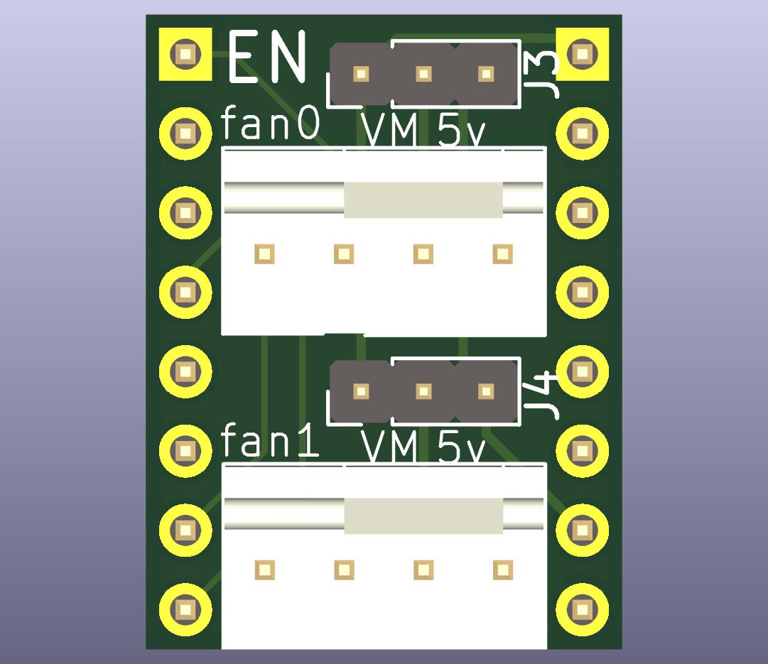
TMTua is smallish board with a single purpose: to connect a 4 pin (Noctua) fan to your printer pcb without having to crimp a custom cable ever again.
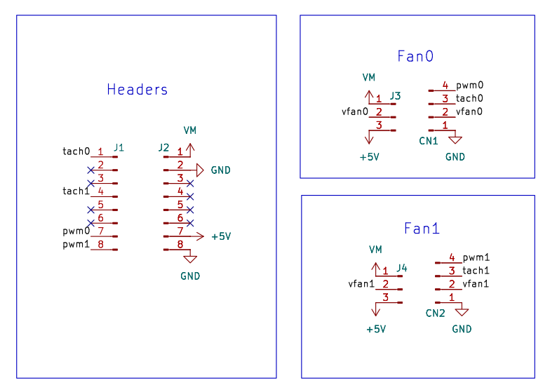
| TMTua Pin | Stepper Driver Pin |
|---|---|
| fan0 | |
| tach0 | EN |
| tach1 | UART1 |
| fan1 | |
| pwm0 | STEP |
| pwm1 | DIR |
[fan_generic fan_1]
pin: PA1
tachometer_pin: ^PD8You can use the Noctua white paper to assess whether the onboard pull-up if there's already one on the EN pin is sufficient for the tach pins and your fans.
The paper outlines the following minimum recommendations:
| Voltage | Pullup Resistor(Ω) |
|---|---|
| 5V | 1k |
| 12V | 2k7 |
| 24V | 12k |
For example, the internal pull-ups on STM32F407 are about 40k which are sufficient for all cases, but the hardware 10k pull-up on EN on my Robin Nano v3 board is too strong for a 24v fan, though fine for 5 and 12v fans.
You can order the board from JLCPCB using the production_files directory.
They're also available on my here.
May not be wired on older boards. On newer boards, you may need to jumper the UART pin under the stepper driver slot to connect it to your mcu. Consult your board's schematic for more information. ↩
| Qty | Value | Footprint | References |
|---|---|---|---|
| 2 | B-2100S08P-A110 | Connector_PinHeader_2.54mm:PinHeader_1x08_P2.54mm_Vertical | J1, J2 |
| 2 | HF1004E | Connector:FanPinHeader_1x04_P2.54mm_Vertical | CN1, CN2 |
| 2 | PZ200V-11-03P | Connector_PinHeader_2.00mm:PinHeader_1x03_P2.00mm_Vertical | J3, J4 |
It measures 15.2 × 20.3 mm and has 2 copper layers, 1.6 mm thick.
6 parts, built around the B-2100S08P-A110, HF1004E and PZ200V-11-03P. The full list of its parts is on this page, with links to each part's symbol and footprint where PCBKit's library has them.
From the willpuckett/tmtua repository on GitHub, at the commit this page was made from: the board is tmtua.kicad_pcb and its schematic tmtua.kicad_sch. PCBKit opens the board in the browser, with nothing to install.
Its repository states no licence, so its author keeps all rights: ask willpuckett before reusing the design.

byrantech/laptop
anyon_e, a highly integrated, high end, open source laptop. Attempt the impossible.


Jcparkyn/dpoint
Open-source digital stylus using camera tracking and inertial measurements

VoronDesign/Voron-Hardware
Cool Hardware designed by the Voron Design group

hoglet67/RGBtoHDMI
Bare-metal Raspberry Pi project that provides pixel-perfect sampling of Retro Computer RGB/YUV video and conversion to HDMI

hackclub/OnBoard
💡 Join 1,000 teenagers and make your first PCB with a $100 grant!

Luos-io/luos_engine
Open-source and real-time orchestrator for cyber-physical-systems, to easily design, test and deploy embedded applications and digital twins.