Skip to the content
PCBKitNew board
2 layers15.2 × 20.3 mmTmceiver, the printed circuit board in 3D

A drop in CAN transceiver for Robin Nano V3

Size
15.2 × 20.3 mm
Copper layers
2
Thickness
1.6 mm
Parts
9
Nets
21
Pads
40
Tracks, vias
71, 5
Pours
1
Routed
Yes
KiCad
KiCad 8.0 (file 20240108)
Created
23 Aug 2024
Updated
17 Apr 2025

Overview

Tmceiver is an open-source printed circuit board by willpuckett, from the willpuckett/tmceiver repository on GitHub. It is a 2-layer board of 15.2 × 20.3 mm with 9 parts on 21 nets, routed with 71 tracks and 5 vias.

It is built around the TCAN1044ADRBRQ1, B-2100S08P-A110 and ACT1210-510-2P-TL00, with the ZX-PZ2.0-1-2PZZ among its other parts. Its parts include 5 connectors, 1 capacitor, 1 resistor, 1 IC and 1 inductor. It belongs with the radio and wireless boards of this library.

Main components

4

README

README.md

TMCeiver

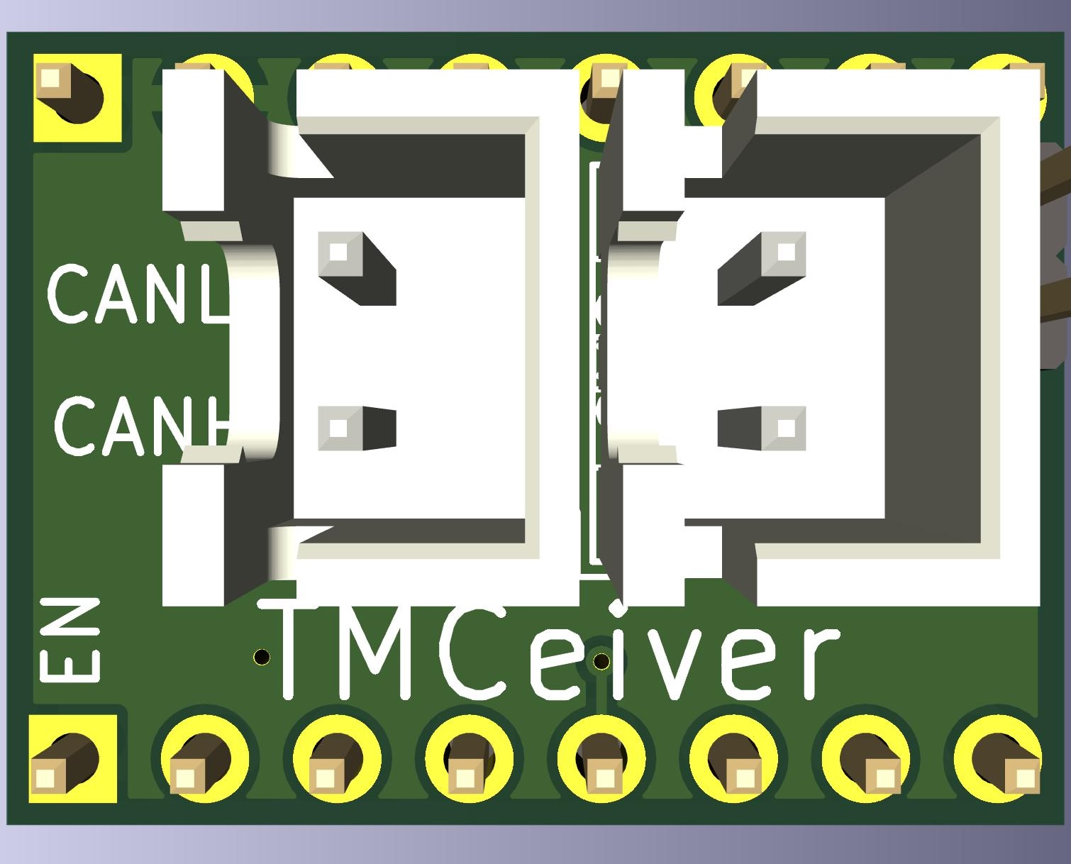
A drop in CAN transceiver for Robin Nano V3.
TMCeiver

TMCeiver utilizes a spare stepper slot on Robin Nano V3 to provide CAN connectivity.

Features

  • CANFD capable (not yet supported in Klipper)
  • Excellent reliability—no CAN retransmits in several months of testing
  • Jumperable 120 Ω termination resistor
  • Less cabling to crimp

Installation

Start with power off.

  1. Remove the stepper driver from the slot you want to use.
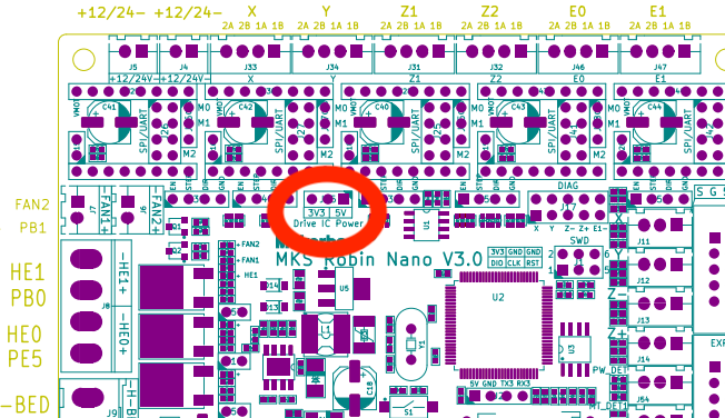
  2. Make sure the steppers are jumpered to run at 5v.
    jumper to 5v
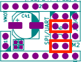
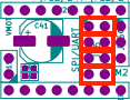
  3. Use jumpers to jump the MISO and SCK pins to the TMCeiver. MISO and SCK are the first and third pins from the mcu side of the stepper slot. If you're not sure, you can jumper the entire row (all four pins).
    MISO & SDK or all pins
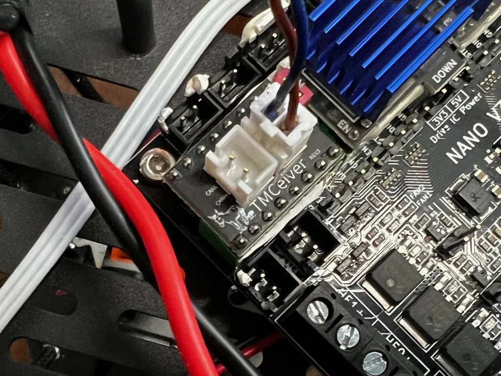
  4. Insert TMCeiver into the slot, aligning the EN silkscreen with the EN slot on the board (for rev3, align the octule icon with EN). If you get it backwards, nothing will be damaged, but it won't work.
    Installed tmceiver
  5. Connect the CAN bus to the JST XH connector.
  6. Terminate the CAN bus by placing a jumper on the pins labeled TERM.
  7. You can connect a second CAN device to the other JST XH connector, in which case you should remove the jumper from the TERM pins and terminate the bus at the last device.
  8. Compile and flash your board (Use pins 'PD0/PD1' for the CAN bus) with the Katapult bootloader. You can build the Katapult Deployer and flash it via SD Card, or follow these instructions to flash with OpenOCD.
  9. Flash Klipper. If you're connecting to the CAN bus with USB via the Robin Nano V3, you'll need to compile in CAN bus bridge mode.

Schematic

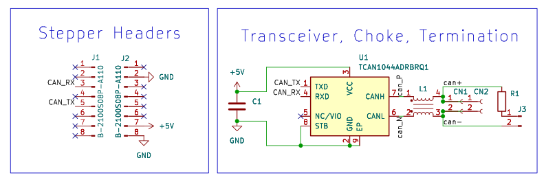
Schematic

Acquisition

Use the files in production_files directory to order the PCB from your favorite board house. If you're trying to lower costs, you can opt for assembly on the bottom side only, and hand solder the top side components.

There's also a couple available from my first run here.

Parts

9
QtyValueFootprintReferences
2B-2100S08P-A110Connector_PinHeader_2.54mm:PinHeader_1x08_P2.54mm_VerticalJ1, J2
2B2B-XH-A (LF)(SN)Connector_JST:JST_XH_B2B-XH-A_1x02_P2.50mm_VerticalCN1, CN2
1ACT1210-510-2P-TL00TDK_ACT1210:CHOKE_10-2P-TL00_TDKL1
1CL10B104KB8NNNCCapacitor_SMD:C_0603_1608MetricC1
1RC0805FR-07120RLResistor_SMD:R_0805_2012MetricR1
1TCAN1044ADRBRQ1Package_SON:VSON-8-1EP_3x3mm_P0.65mm_EP1.65x2.4mmU1
1ZX-PZ2.0-1-2PZZConnector_PinHeader_2.00mm:PinHeader_1x02_P2.00mm_VerticalJ3

Questions

How big is the Tmceiver PCB?

It measures 15.2 × 20.3 mm and has 2 copper layers, 1.6 mm thick.

What parts does the Tmceiver use?

9 parts, built around the TCAN1044ADRBRQ1, B-2100S08P-A110, ACT1210-510-2P-TL00 and ZX-PZ2.0-1-2PZZ. The full list of its parts is on this page, with links to each part's symbol and footprint where PCBKit's library has them.

Where can I download the Tmceiver KiCad files?

From the willpuckett/tmceiver repository on GitHub, at the commit this page was made from: the board is tmceiver.kicad_pcb and its schematic tmceiver.kicad_sch. PCBKit opens the board in the browser, with nothing to install.

Can I use the Tmceiver design in my own project?

Its repository states no licence, so its author keeps all rights: ask willpuckett before reusing the design.

Similar boards

  • 2 layers15.2 × 20.3 mmTmtua, the printed circuit board in 3D

    Tmtua

    willpuckett/tmtua

    A drop-in connector for your quiet storm

    6 parts
  • 8 layers123.5 × 58 mmBLDC MC V1.0, the printed circuit board in 3D

    BLDC MC V1.0

    AhmedAbo-Eita/BLDC_Motor_Driver

    BLDC Motor Driver hardware and firmware project including power stage, gate driver, protection circuits, and control firmware for sensor-based and/or sensorless BLDC motors.

    234 parts1
  • 2 layers30 × 100 mmEKSP CAN, the printed circuit board in 3D

    EKSP CAN

    Konstantin-Dudersky/plc-modules

    После открыть файл в Inkscape и изменить размер страницы

    15 parts
  • 2 layers103 × 30.5 mmTS Back Endcap, the printed circuit board in 3D

    TS Back Endcap

    EEVengers/ThunderScope

    ThunderScope GitHub Repo

    9 parts1.3kMIT
  • 2 layers31.8 × 47.6 mmNGC 38 connector, the printed circuit board in 3D

    NGC 38 connector

    rusefi/rusefi

    rusefi - GPL internal combustion engine control unit

    9 parts1.2k
  • 2 layers24 × 27.3 mmExpansion Card Retrofit, the printed circuit board in 3D

    Expansion Card Retrofit

    FrameworkComputer/ExpansionCards

    Reference designs and documentation to create Expansion Cards for the Framework Laptop

    9 parts1.1kCC-BY-4.0
  • 2 layers15.6 × 17.3 mmSKR Mini TFT Thermistor Board, the printed circuit board in 3D

    SKR Mini TFT Thermistor Board

    VoronDesign/Voron-Hardware

    Cool Hardware designed by the Voron Design group

    9 parts1.1kGPL-3.0
  • 2 layers39.1 × 49.5 mmLearnoliver, the printed circuit board in 3D

    Learnoliver

    hackclub/OnBoard

    💡 Join 1,000 teenagers and make your first PCB with a $100 grant!

    9 parts915